 Skip to content
by Jayden
Senior Electronics Engineer
What is a Copper Core PCB?
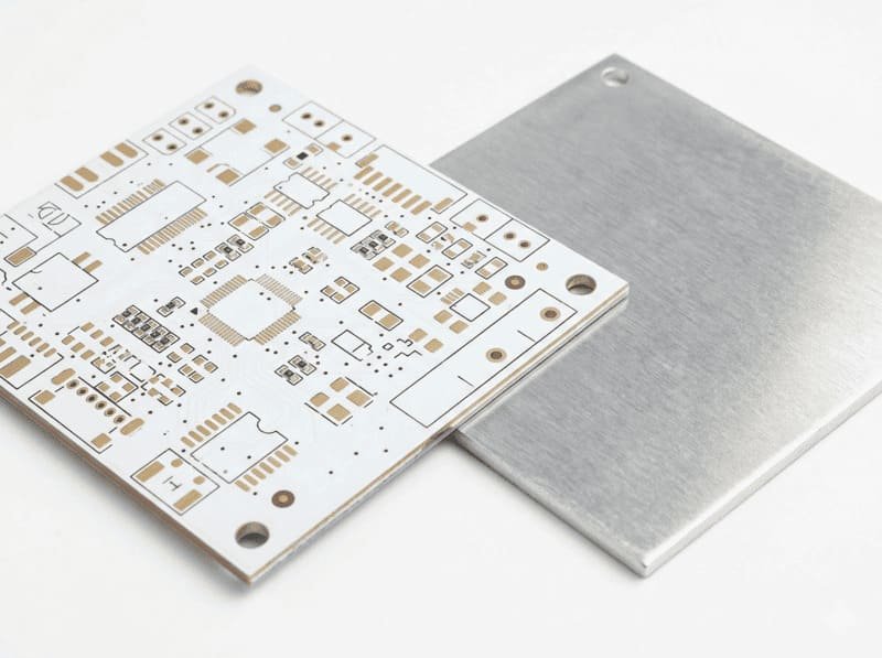
A copper core PCB is a specialized printed circuit board that uses a solid copper layer as its base material instead of traditional FR4 fiberglass. I’ve worked with many clients who needed exceptional thermal management for their power electronics, and copper core PCBs have consistently proven to be the superior solution. These boards feature a thick copper layer (typically 1mm to 3mm) sandwiched between dielectric materials and copper foil layers, creating a highly effective thermal conductor at the heart of the circuit board.
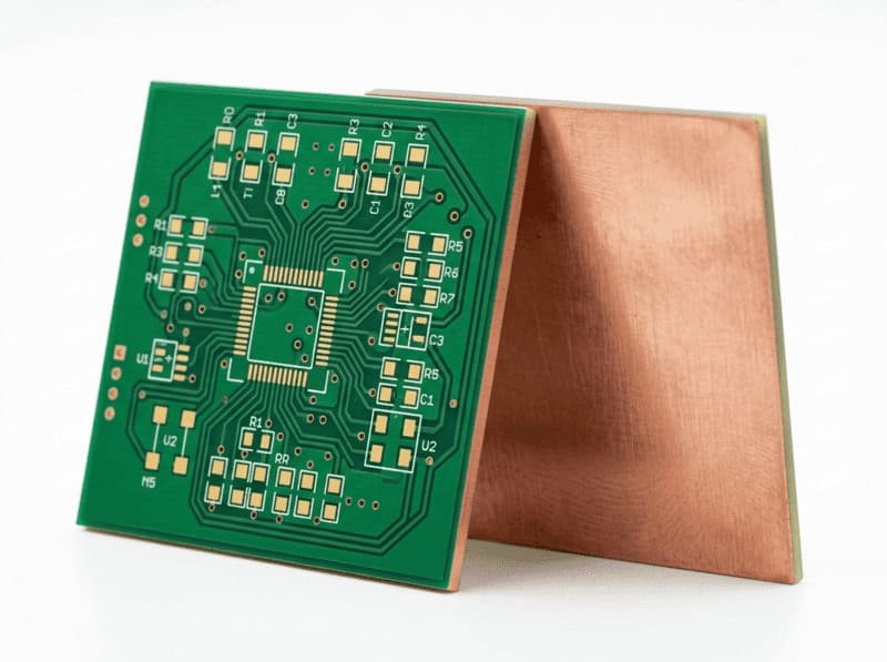
The copper core serves as both the structural foundation and a highly efficient heat spreader. It rapidly draws heat away from components and distributes it across the entire board area. This technology is fundamentally different from standard FR4 boards with heavy copper or thermal vias, as it provides a solid metallic pathway for heat directly through the board’s center.
What are the advantages of Copper Core PCB?
Superior Thermal Conductivity
Copper core PCBs offer thermal conductivity that's up to 20 times higher than traditional FR4 boards. This makes a dramatic difference for industrial control systems that handle significant power. I recently worked with a German automation manufacturer who was experiencing overheating issues in their motor control modules. By switching to a copper core design, we reduced junction temperatures by 35°C while maintaining the same power output.
The thermal conductivity of copper (approximately 400 W/m·K) far exceeds that of FR4 (about 0.3 W/m·K), creating a thermal superhighway that efficiently moves heat away from sensitive components. This allows your industrial equipment to operate at full capacity without thermal throttling or reliability concerns.
Enhanced Power Handling Capability
For industrial automation equipment that manages significant current, copper core PCBs provide substantial advantages in power handling. The copper substrate can safely carry much higher currents than standard PCBs, making these boards ideal for power supply modules, motor controllers, and high current distribution circuits.
The increased thermal efficiency also allows components to operate closer to their maximum ratings without overheating. This enables more compact designs without sacrificing performance, a critical advantage for modern industrial equipment where space is often at a premium.
Exceptional Mechanical Stability
Industrial environments demand robust electronics that can withstand mechanical stress and temperature fluctuations. Copper core PCBs provide superior dimensional stability compared to standard FR4 boards, with a coefficient of thermal expansion (CTE) that closely matches many electronic components.
The solid metal core significantly reduces board warping during temperature cycles, maintaining the integrity of solder joints and component connections. For equipment operating in harsh factory environments with wide temperature variations, this translates to improved long term reliability and reduced maintenance costs.
What is Copper Core PCB commonly used in?
High Power LED Lighting Systems
Industrial LED lighting applications benefit tremendously from copper core PCBs. The excellent thermal management properties allow LEDs to operate at maximum brightness without overheating, extending their useful life significantly. Factory lighting, machine vision systems, and specialized illumination equipment all gain reliability and performance advantages from copper core technology.
I’ve helped several clients transition their industrial lighting systems to copper core designs, resulting in 40% longer operational life and 25% higher maximum brightness without increasing junction temperatures. The enhanced reliability is particularly valuable in manufacturing environments where lighting maintenance creates costly production disruptions.
Motor Drive Controllers
Modern industrial automation relies heavily on sophisticated motor control systems that generate substantial heat during operation. Copper core PCBs provide the thermal management these systems need to operate reliably under continuous heavy loads.
The excellent current carrying capacity of copper core boards also makes them ideal for the high power sections of variable frequency drives and servo controllers. By maintaining lower operating temperatures, these critical components experience fewer thermal related failures and deliver more consistent performance over their operational lifetime.
Power Converters and Supplies
Industrial power supplies and DC-DC converters benefit from the superior thermal performance of copper core PCBs. The efficient heat dissipation allows power components to operate more efficiently, reducing energy waste and improving overall system reliability.
For switching power supplies operating at high frequencies, copper core boards provide another significant advantage: improved EMI (Electromagnetic Interference) shielding. The copper substrate can be grounded to create an effective shield against electromagnetic noise, helping your industrial equipment meet stringent EMC requirements.
High Frequency RF Circuits
Copper core PCBs offer exceptional performance for high frequency applications like industrial wireless communications systems. The copper substrate provides excellent grounding and shielding characteristics that help maintain signal integrity in noisy industrial environments.
The superior thermal properties also benefit RF power amplifiers, allowing them to operate at higher power levels without thermal issues. This enables more reliable wireless communications across factory floors and between equipment modules, supporting the growing demands of Industry 4.0 connectivity.

Design Guidelines for Optimal Copper Core PCB Performance

Component Placement Optimization
Strategic component placement dramatically impacts the thermal performance of copper core PCBs. I always recommend:
1. Distributing high power components across the board rather than clustering them
2. Placing the hottest components where they can make the best use of the copper core’s thermal properties
3. Considering the final installation orientation to leverage natural convection cooling
4. Leaving adequate space between heat generating components to prevent thermal hotspots
For industrial control systems, this thoughtful thermal layout can improve overall system reliability by ensuring more uniform temperature distribution across critical components.
Thermal Simulation and Validation
Before manufacturing, we recommend thermal simulation to validate the design’s performance. Modern simulation tools can accurately predict component temperatures and identify potential hotspots before production. At LZJPCB, we offer thermal simulation services to help optimize your design for the best performance.
After manufacturing, thermal imaging verification ensures the actual performance matches expectations. This validation step identifies any issues before the boards are integrated into your industrial equipment, preventing costly field failures and redesigns.
Surface Finish Considerations
The choice of surface finish impacts both the thermal performance and reliability of copper core PCBs. For industrial applications requiring the best thermal performance, we typically recommend:
ENIG (Electroless Nickel Immersion Gold) for excellent solderability and thermal conductivity
Immersion silver for superior electrical conductivity and good thermal performance
OSP (Organic Solderability Preservative) for cost effective solutions with good thermal characteristics
The right surface finish selection balances thermal performance with your specific manufacturing and environmental requirements.
High Frequency RF Circuits
Copper core PCBs offer exceptional performance for high frequency applications like industrial wireless communications systems. The copper substrate provides excellent grounding and shielding characteristics that help maintain signal integrity in noisy industrial environments.
The superior thermal properties also benefit RF power amplifiers, allowing them to operate at higher power levels without thermal issues. This enables more reliable wireless communications across factory floors and between equipment modules, supporting the growing demands of Industry 4.0 connectivity.
Manufacturing Considerations for Copper Core PCBs
Material Selection and Stackup Design
Creating effective copper core PCBs requires careful material selection and stackup planning. At LZJPCB, we typically use specialized high temperature dielectric materials that bond securely to the copper substrate while providing the necessary electrical isolation. These materials must withstand the thermal stresses of both the manufacturing process and operational conditions.
The stackup design must balance thermal performance with electrical requirements. I work closely with our industrial clients to determine the optimal copper core thickness and layer configuration based on their specific thermal demands, ensuring the final design meets both electrical and thermal requirements without unnecessary cost increases.

Specialized Fabrication Techniques

Manufacturing copper core PCBs requires specialized equipment and expertise not found in standard PCB facilities. The copper base material presents unique challenges in drilling, etching, and lamination processes. At LZJPCB, we’ve invested in the specific equipment and developed the manufacturing processes needed to produce high quality copper core boards consistently.
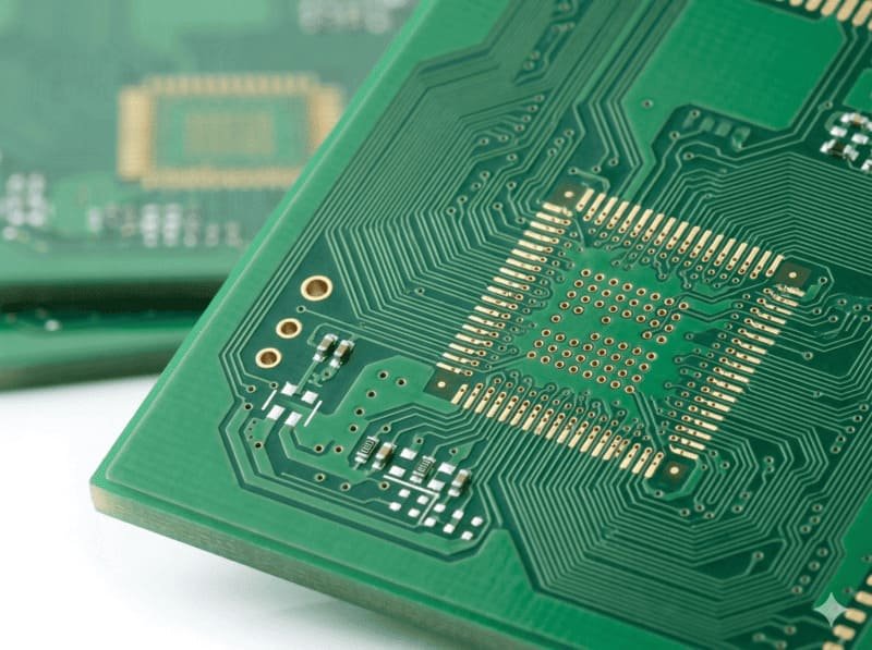
Drilling through the copper core requires special drill bits and carefully controlled drilling parameters to prevent burring and maintain hole quality. Our precision drilling equipment maintains tight tolerance even when penetrating thick copper layers, ensuring reliable plated through holes that meet IPC standards.
Thermal Via Design and Implementation
Strategic placement of thermal vias is critical for maximizing the effectiveness of copper core PCBs. These vias create direct thermal paths from heat generating components to the copper core, dramatically improving heat transfer efficiency.
For optimal thermal performance, we recommend:
Placing thermal vias directly under hot components
Using appropriate via size and density based on thermal load
Implementing proper copper plating in vias to maximize thermal conductivity
Creating thermal patterns that efficiently spread heat into the copper core
I’ve helped many clients optimize their thermal via designs based on computational thermal modeling, achieving significantly better performance than standard approaches.

Comparing Copper Core PCBs to Alternative Solutions
What is the difference between Copper Core PCB and FR4 PCB?

While standard FR4 boards are sufficient for many applications, they simply cannot match the thermal performance of copper core PCBs for high power designs. FR4 has a thermal conductivity approximately 1000 times lower than copper, creating a significant thermal bottleneck in power intensive applications.
For industrial automation equipment operating in confined spaces or enclosures with limited airflow, this difference becomes critical. Copper core boards can often eliminate the need for additional cooling systems, reducing system complexity, power consumption, and potential points of failure.
What is the difference between Copper Core PCB and Metal Core (Aluminum) PCB?

Aluminum core PCBs are another thermal management solution, but they offer only about half the thermal conductivity of copper core boards (approximately 200 W/m·K vs. 400 W/m·K). For the most demanding applications where every degree matters, copper core provides superior performance.
The higher thermal mass of copper also creates more stable operating temperatures with fewer thermal cycles during intermittent operation. This reduces thermal stress on components and solder joints, extending the overall system reliability, particularly valuable for industrial equipment expected to operate continuously for years.
What is the difference between Copper Core PCB and Ceramic PCB?

Ceramic substrates (like aluminum nitride or aluminum oxide) offer excellent thermal properties but at significantly higher costs than copper core solutions. For most industrial applications, copper core PCBs provide the optimal balance of thermal performance and manufacturing practicality.
Copper core boards are also much less brittle than ceramic substrates, making them more suitable for industrial environments where equipment may experience mechanical shock or vibration. The improved durability translates directly to better field reliability and lower maintenance costs.
LZJPCB Copper Core PCB Manufacturing Capabilities
| Features | Capabilities |
|---|---|
| Copper Core Thickness | 0.5mm to 3.0mm |
| Maximum Board Size | 600mm × 500mm |
| Copper Foil Thickness | 1oz to 10oz (35μm to 350μm) |
| Layer Count | 1-16 layers |
| Minimum Line Width/Spacing | 3mil/3mil (0.076mm/0.076mm) |
| Surface Finishes | ENIG, Immersion Silver, OSP, Hard Gold, Immersion Tin |
| Thermal Vias | Down to 0.2mm diameter with full copper plating |
| Dielectric Materials | High-Tg FR4, Polyimide, Special High-Temperature Materials |
| IPC Standards Compliance | IPC-A-600 Class 2 and 3, IPC-6012 |
| Thermal Conductivity | Up to 400 W/m·K |
| Testing Procedures | 100% Electrical Testing, Thermal Performance Validation |
Why Choose LZJPCB for Copper Core PCB?
Specialized Technical Expertise
At LZJPCB, we've been manufacturing advanced thermal management PCBs for over 15 years. Our engineering team specializes in copper core technology and understands the unique challenges these boards present. I personally work with many of our industrial clients to ensure their designs maximize the benefits of copper core technology.
We provide comprehensive design guidance and thermal optimization recommendations based on your specific application requirements. This collaborative approach ensures your final product achieves the best possible thermal performance and reliability.
Advanced Manufacturing Capabilities
Our production facility features specialized equipment specifically for copper core PCB manufacturing, including:
High precision drilling systems for accurate processing of thick copper cores
Advanced lamination presses with precise temperature and pressure control
Automated optical inspection systems calibrated for copper core specifications
Thermal testing equipment to validate performance before shipment
These capabilities allow us to maintain tight quality control throughout the manufacturing process, ensuring consistent performance across production runs.
Comprehensive Quality Assurance
Every copper core PCB we produce undergoes rigorous testing to verify both electrical integrity and thermal performance. Our quality assurance process includes:
100% electrical testing using flying probe or dedicated test fixtures
Thermal imaging validation under simulated load conditions
Cross sectional analysis to verify internal construction quality
Material composition verification to ensure thermal conductivity meets specifications
This comprehensive testing ensures the boards will perform as expected in your industrial equipment, preventing costly field failures and warranty issues.
Copper Core PCB FAQ
How thick does the copper core need to be for effective thermal management?
The optimal copper core thickness depends on your specific thermal requirements, but most industrial applications use cores between 1mm and 3mm thick. I typically recommend starting with a 1mm core for moderate thermal loads and increasing to 2mm or 3mm for high power applications. The relationship between thickness and thermal performance isn’t strictly linear, doubling the core thickness doesn’t double the thermal performance, but it does provide a significant improvement. For precise sizing, we conduct thermal simulations based on your component power dissipation and maximum allowable temperatures. This ensures you get effective thermal management without unnecessarily increasing weight and cost with an oversized core.
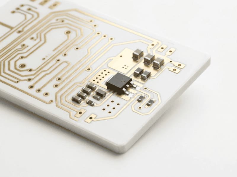
Can copper core PCBs be used with surface mount technology (SMT) components?
Absolutely! Copper core PCBs work excellently with SMT components and modern assembly processes. In fact, the superior thermal properties of copper core boards make them ideal for densely populated SMT designs where heat management is critical. We regularly produce copper core boards that undergo standard reflow soldering with no issues. The only special consideration is that the higher thermal mass requires slightly modified reflow profiles with longer preheat stages. Our manufacturing team provides recommended profiles based on your specific board design and component mix. I’ve seen some of our most successful copper core implementations in industrial controllers using fine pitch BGAs and other advanced SMT packages that generate significant heat.
How do I design thermal vias for optimal heat transfer to the copper core?
Effective thermal via design is crucial for maximizing the performance of copper core PCBs. I recommend these key practices:
1. Use a grid pattern of vias directly under heat generating components with 1.0-1.5mm spacing
2. Make thermal vias as large as practical (typically 0.3-0.5mm diameter) while respecting component pad requirements
3. Ensure vias are fully plated with copper for maximum thermal conductivity
4. Create large copper pads on internal layers connected to these vias to spread heat horizontally
The exact pattern depends on your specific components and thermal loads. For particularly critical applications, we can perform thermal simulations to optimize the via pattern. One industrial client reduced their MOSFET junction temperature by an additional 15°C just by optimizing their thermal via pattern based on our recommendations.
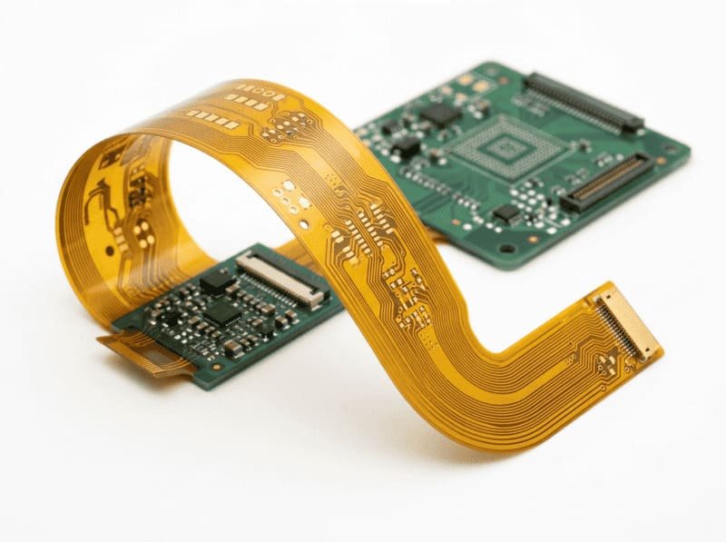
Can copper core PCBs be used in flexible or rigid flex designs?
Standard copper core PCBs are not suitable for flexible applications due to the rigid nature of the thick copper substrate. However, we can create hybrid designs that combine rigid copper core sections with flexible interconnects. These designs provide excellent thermal management in the rigid sections while allowing for flexible connections between boards. For industrial equipment with space constraints requiring both thermal management and flexible connections, these hybrid solutions offer an excellent compromise. I recently worked with a robotics manufacturer who used this approach for their motor control modules, allowing them to fold the control electronics into a compact housing while maintaining excellent thermal performance.
How does the reliability of copper core PCBs compare to standard FR4 in harsh environments?
Copper core PCBs significantly outperform standard FR4 boards in harsh industrial environments, particularly in conditions involving temperature cycling, vibration, and mechanical stress. The copper substrate provides much better dimensional stability during temperature changes, reducing stress on component solder joints. Our reliability testing shows up to 3x improvement in thermal cycling endurance compared to standard FR4 boards of similar thickness. The copper core also provides better mechanical rigidity, reducing board flexing that can damage components or traces during vibration. For industrial equipment operating in factory environments with wide temperature variations and mechanical stress, copper core PCBs typically show substantially improved mean time between failures (MTBF). One manufacturing client reported a 70% reduction in field failures after switching to copper core designs for their factory automation equipment.
Unlock More Possibilities with LZJPCB Solutions
From standard rigid PCBs to advanced rigid flex technologies, our manufacturing services deliver exceptional quality across diverse applications and industries.
Flex PCB
- Layer count: 1-32 layers
- Turn time: from 24 hours
- Thickness: 0.4mm-4.0mm
- Copper: 1-15oz
- Min trace/spacing: 3/3 mil
HDI PCB
- 4-20 layer HDI designs
- Advanced buried and blind via technology
- 10 day production timeline
- Ideal for complex, space constrained applications
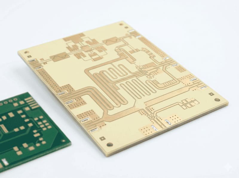
Rogers PCB
- 5 day production timeline
- Premium RO4003C and RO4350B materials
- Specialized for RF and high frequency applications
- Exceptional signal integrity performance
Aluminum PCB
- 1-2 layer designs
- 24 hour rapid production available
- Thickness options: 0.8mm-3.2mm
- Copper weights: 0.5-4oz
- Precision trace/spacing down to 3/3 mil
- Enhanced thermal dissipation
Ceramic PCB
- Layer count: 1-2 layers
- Turn time: from 24 hours
- Thickness: 0.8mm-3.2mm
- Copper: 0.5-4oz
- Min trace/spacing: 3/3 mil
Get Your Turnkey PCB Manufacturing Quote Within 12 Hours
Our experienced engineering team will analyze your requirements and provide a detailed production plan with transparent pricing.
