 Skip to content
 Rigid-Flex PCB Manufacturer
The Versatile Solution for Modern Electronics Design
What is a Rigid Flex PCB?
A rigid-flex PCB combines traditional rigid circuit boards with flexible polyimide based circuits in a single integrated structure. This hybrid technology joins solid FR4 sections with bendable polyimide areas, creating a continuous circuit that eliminates the need for connectors between board sections. I’ve seen firsthand how these boards maintain signal integrity across bend zones while enabling three dimensional designs that would be impossible with conventional PCBs.
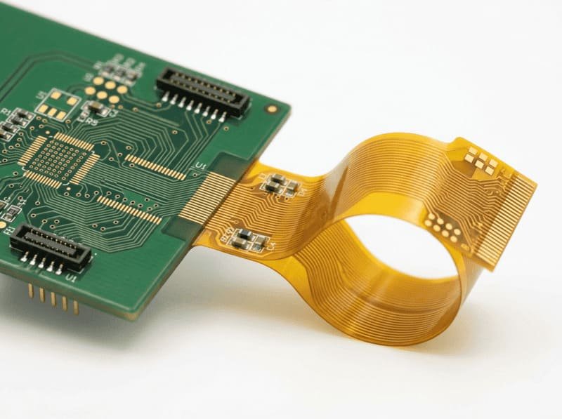
At LZJPCB, our rigid-flex PCBs feature precision manufactured copper traces that flow seamlessly between rigid and flexible sections, maintaining electrical continuity throughout. The rigid sections provide stable mounting areas for components, while the flexible portions allow movement, folding, and three dimensional configurations. This technology has revolutionized electronic design for industrial automation equipment, medical devices, aerospace systems, and any application where space constraints and reliability are critical concerns.
What are the advantages of rigid flex PCB?
Space and Weight Optimization
Rigid-flex PCBs reduce assembly volume by up to 60% compared to traditional interconnected board solutions. The elimination of connectors and cables creates significantly more compact assemblies, perfect for space constrained industrial control systems. I recently worked with a German automation client who reduced their control module size by 40% while maintaining all functionality by switching to a rigid flex design.
The weight savings are equally impressive, typically 30-50% lighter than equivalent multi board assemblies due to the elimination of connectors, mounting hardware, and cables. This makes rigid flex PCBs ideal for mobile and portable industrial equipment where every gram matters.
Enhanced Reliability Through Reduced Connections
By eliminating traditional board to board connectors, rigid-flex PCBs remove the most common failure points in electronic assemblies. Our manufacturing data shows connection failures account for over 60% of field issues in industrial electronics. Rigid-flex technology directly addresses this by providing continuous electrical pathways across rigid and flexible sections.
The elimination of soldered connections between separate boards dramatically improves vibration resistance, critical for industrial equipment operating in high vibration environments. The flexible sections actually absorb mechanical stress rather than transferring it to soldered joints, extending product lifespan significantly in harsh conditions.
Simplified Assembly and Reduced Manufacturing Complexity
Rigid-flex PCBs arrive as pre connected assemblies, eliminating manual connector installation and wire harnessing. This typically reduces assembly time by 40-60% while minimizing opportunities for human error during production. The technology essentially delivers a pre assembled 3D circuit solution that simplifies manufacturing logistics significantly.
The reduction in part count (no connectors, cables, or mounting hardware) means fewer components to source, inventory, and manage, simplifying supply chains and reducing potential points of failure. For industrial automation manufacturers dealing with complex assemblies, this streamlined approach creates significant production advantages.
What is Rigid Flex PCB commonly used in?
Rigid-flex PCBs excel in industrial control equipment where reliability in harsh conditions is essential. The technology's resistance to vibration, thermal cycling, and mechanical stress makes it ideal for factory automation systems that must operate continuously for years without failure. The compact form factor allows control modules to be integrated directly into machinery where traditional PCB assemblies wouldn't fit.
I've personally supported projects where rigid-flex allowed sensors and processing electronics to be integrated into robotic end effectors where the constant articulation would quickly damage traditional wired connections. The flexible sections withstand millions of bend cycles while maintaining perfect electrical continuity, a level of durability that's simply impossible with conventional interconnect methods.
The medical device industry has widely adopted rigid flex technology due to its reliability, miniaturization capabilities, and biocompatibility options. Implantable medical devices particularly benefit from rigid-flex's small form factor and elimination of failure prone connections. For equipment like ultrasound probes and endoscopes, rigid flex enables sophisticated electronics to fit into extremely compact forms while withstanding repeated sterilization cycles.
Portable diagnostic equipment benefits from rigid flex's ability to create ergonomic, three dimensional electronic packages that are lightweight and durable. The technology's inherent resistance to mechanical fatigue ensures reliable operation even in devices that experience frequent handling and movement between patients.
In aerospace applications, rigid flex PCBs deliver the perfect combination of reliability and weight reduction. With weight savings directly translating to fuel efficiency and operational range, the technology offers compelling advantages for aircraft systems. The robust resistance to vibration and thermal cycling ensures consistent performance in the extreme conditions experienced during flight.
Military electronics similarly benefit from rigid-flex's durability and compact design. Battlefield equipment must withstand shock, vibration, and harsh environmental conditions while maintaining full functionality. The elimination of connection points significantly reduces failure risks in mission critical systems where reliability can be a matter of life and death.

Rigid Flex PCB Design Considerations
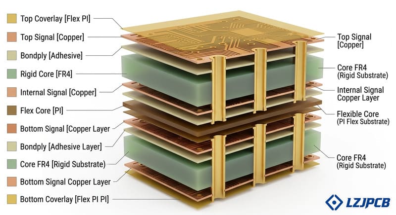
Proper material selection is crucial for rigid-flex performance. The rigid sections typically use FR4 or polyimide based materials, while the flexible portions require specialized polyimide films with adhesiveless copper bonding for maximum bend reliability. At LZJPCB, we recommend specific materials based on your application's bend requirements, operating temperature, and expected lifecycle.
Stackup design requires careful consideration of neutral bend axis placement to minimize stress on copper traces during flexing. Unlike standard multilayer boards, rigid-flex stackups must account for different material properties across sections and maintain controlled impedance across transitions. Our engineering team has developed specialized simulation tools to optimize layer arrangements for maximum reliability in dynamic applications.
The transition area between rigid and flexible sections requires special attention to prevent delamination and stress concentration. We implement gradual transition zones with specialized adhesion promotion techniques to ensure long term reliability at these critical interfaces. Based on decades of manufacturing experience, we recommend specific bend radii guidelines (typically 10x the flexible circuit thickness as minimum) to prevent copper fatigue and cracking.
For applications requiring repeated flexing, we implement dynamic bend areas with special design rules, including:
Copper traces running perpendicular to the bend axis when possible
Staggered trace arrangements to distribute stress
Specialized copper finishing processes to maximize flex life
Strain relief features near the rigid flex transition
Rigid-flex PCB manufacturing involves significantly more complex processes than standard rigid boards. The materials require precise registration between layers, specialized lamination cycles, and careful handling throughout production. At LZJPCB, our dedicated rigid-flex production lines maintain tight process controls to ensure consistent quality across production runs.
The coverlays (flexible equivalents of solder mask) require precise alignment and specialized adhesion techniques to maintain integrity through environmental exposure and flexing. Our advanced manufacturing processes include specialized plasma treatment and proprietary adhesion enhancement steps that dramatically increase coverlay reliability compared to standard industry practices.
Types of Rigid Flex PCB Constructions
Type I: Flex with Stiffeners

This simplest form consists primarily of flexible circuit with rigid areas created by bonding FR4 stiffeners to provide component mounting surfaces. This construction offers excellent flexibility with minimal thickness but is typically limited to less complex circuits. It’s ideal for applications where weight and thickness are critical concerns, providing rigid mounting areas only where absolutely necessary.
Type II: Traditional Rigid Flex
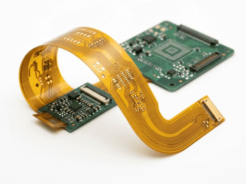
The most common construction features flexible circuits extending from multilayer rigid sections, with the flex portion typically having 1-2 signal layers. This balanced design provides good flexibility while allowing complex circuitry in the rigid sections. Industrial automation control systems frequently use this construction for its versatility and reliability in connecting multiple rigid board sections.

Type III: Multilayer Flex Construction

The most sophisticated design incorporates multilayer flexible circuits (3+ layers) connecting multilayer rigid sections. This premium construction enables complex signal routing through flexible areas, essential for high density applications where significant circuit functionality must extend across bend zones. While more challenging to manufacture, Type III rigid flex enables the most complex three dimensional electronic packages for space constrained applications.
Type IV: Rigid Flex with Embedded Components
An advanced variation incorporates embedded components within the layers of the rigid sections, further maximizing space utilization. This construction is ideal for extremely compact designs where every cubic millimeter matters. The embedding process requires specialized manufacturing techniques that LZJPCB has perfected through years of development.

What is the difference with Rigid Flex PCB?
What is the difference between Rigid Flex PCB and Traditional PCB?

Rigid flex PCBs eliminate the need for board to board connectors, removing the most common failure points in electronic assemblies. While traditional PCBs with connectors may have lower initial material costs, the total assembly cost often favors rigid flex when considering connector components, assembly labor, and increased reliability. The elimination of connectors also significantly reduces electromagnetic interference issues that plague high speed designs using traditional interconnects.
For industrial applications requiring high reliability in harsh environments, rigid flex provides demonstrably higher MTBF (Mean Time Between Failures) rates compared to connector based solutions. The continuous copper traces across flexible sections maintain perfect signal integrity without the impedance discontinuities introduced by connectors.
What is the difference between Rigid Flex PCB and Flexible PCB with Stiffeners?

While flexible PCBs with stiffeners can provide some of the three dimensional capabilities of rigid flex, they lack the structural integrity and component density capabilities of true rigid flex construction. Flexible circuits typically limit component placement to one or two sides, while rigid flex allows complex multilayer component mounting in the rigid sections.
The manufacturing processes also differ significantly, flexible PCBs with stiffeners involve additional assembly steps to attach discrete stiffeners, while rigid flex creates an integrated structure during the lamination process. This integration provides superior reliability and dimensional stability compared to assembled stiffener solutions.
What is the difference between Rigid Flex PCB and able Assemblies?

Traditional cable assemblies require multiple manufacturing steps: PCB fabrication, cable preparation, and connector assembly. Rigid flex replaces this with a single integrated manufacturing process, eliminating potential quality variations between suppliers and assembly steps. The electrical performance is also superior, cable assemblies introduce impedance discontinuities at each connection point, while rigid flex maintains consistent transmission line characteristics across the entire circuit.
For industrial automation applications involving dynamic movement, rigid flex provides up to 10x longer flex life than typical cable assemblies due to the polyimide material’s superior flex endurance. The elimination of crimped or soldered connections also removes common failure points that plague cable assemblies in high vibration environments.
LZJPCB FR4 PCB Manufacturing Capabilities
| Features | Capabilities |
|---|---|
| Layer Count | Up to 20 layers total (rigid sections), up to 6 layers in flexible sections |
| Rigid Board Thickness | 0.4mm to 3.2mm |
| Flex Circuit Thickness | 0.1mm to 0.3mm |
| Minimum Trace/Space | 3/3 mil (0.076mm) standard, down to 2/2 mil (0.051mm) for advanced designs |
| Surface Finish Options | ENIG, Immersion Silver, OSP, Immersion Tin, Hard Gold |
| Minimum Hole Size | 0.2mm mechanical drilling, 0.1mm laser drilling for microvias |
| Flexible Materials | AP, LF, FR, GF series polyimide films with adhesiveless or adhesive based construction |
| Rigid Materials | Standard FR4, High Tg FR4, Halogen free FR4, Rogers, Polyimide based rigid materials |
| Minimum Bend Radius | 10x material thickness for dynamic applications, 6x for static applications |
| Dynamic Flex Life | Up to 1,000,000 cycles for optimized designs with appropriate bend radius |
| Assembly Options | SMT component assembly on both rigid and flexible sections with specialized processes |
| Stiffener Options | FR4, Polyimide, Aluminum, Stainless Steel |
| Quality Testing | 100% electrical testing, AOI inspection, cross section analysis, flex testing validation |
| Typical Lead Times | Prototype: 5-7 days, Standard Production: 10-15 days, Volume Production: 15-20 days |
| Special Features | Controlled impedance (±10%), selective gold plating, embedded components, mixed materials |
Why Choose LZJPCB for Rigid Flex PCB?
Specialized Engineering Support
Our rigid-flex engineering team brings over 30 years of combined experience in advanced PCB technologies. We don't just manufacture your design, we collaborate with your team to optimize it for reliability and manufacturability. For every rigid flex project, we provide comprehensive design rule guidance specific to your application requirements, identifying potential issues before they impact production.
I personally work with many of our industrial automation clients during the design phase, providing insights on material selection, bend radius optimization, and transition zone design that significantly improve manufacturing yields and long term reliability. Our DFM (Design for Manufacturing) reviews include specialized rigid flex considerations often overlooked by general PCB design tools.
Advanced Manufacturing Capabilities
LZJPCB has invested in dedicated rigid-flex production lines with specialized equipment not found in standard PCB facilities. Our precision registration systems maintain layer to layer alignment within ±0.025mm, critical for reliable plated through holes in rigid flex constructions. Our manufacturing processes include proprietary adhesion enhancement techniques that significantly improve the bond strength between rigid and flexible sections. For industrial clients with demanding applications, we offer specialized testing beyond industry standards, including dynamic flex testing that simulates actual use conditions. Each rigid flex PCB undergoes comprehensive electrical testing and visual inspection to ensure perfect functionality and appearance before shipping.
Proven Success with Industrial Clients
Our portfolio includes successful rigid flex projects for leading industrial automation companies worldwide. We've helped clients reduce control system size by up to 60% while improving reliability through elimination of connectors and cables. Our manufacturing processes meet the stringent requirements of international standards including IPC-6013 Class 2 and 3 for rigid-flex circuits. Working with industrial clients across Europe, Asia, and North America has given us deep insight into the specific requirements of industrial control systems. We understand the importance of long term reliability in factory environments, where equipment may operate continuously for years with minimal maintenance. Our rigid flex solutions are specifically engineered to excel in these demanding conditions.
Rigid-Flex PCB FAQ
What design software is recommended for rigid flex PCB design?
Most major EDA platforms including Altium Designer, Cadence Allegro, and Mentor Xpedition offer rigid flex design capabilities. The key is using software that properly supports separate stackup definitions for rigid and flexible regions. At LZJPCB, we find Altium Designer particularly effective for rigid flex work due to its dedicated rigid flex mode that visualizes board folding in 3D. This helps designers identify potential interference issues before production.
For clients new to rigid flex design, our engineering team provides template stackups and design rule files optimized for your specific software platform. We can also review your design files before production to ensure they follow rigid flex best practices, regardless of which design tool you use.
How many flex cycles can rigid flex PCBs withstand?
The flex endurance depends significantly on design factors including bend radius, copper thickness, and whether the application requires dynamic (repeated) or static (install once) flexing. For static applications with proper design, the flexible sections will maintain integrity for the entire product lifecycle. For dynamic applications, properly designed rigid flex circuits can withstand:
Over 1,000,000 cycles for flex sections with single sided circuitry and optimized trace routing
100,000 to 500,000 cycles for double sided flex circuits with staggered traces
10,000 to 50,000 cycles for multilayer flex sections with appropriate design considerations
To maximize flex life, we implement specialized design techniques including:
Routing traces perpendicular to bend axes when possible
Using rolled annealed copper instead of electrodeposited copper
Implementing teardrop reinforcements at trace junctions
Specifying appropriate bend radii (typically 10x the flexible circuit thickness)
What are the cost considerations compared to traditional PCB solu
What are the cost considerations compared to traditional PCB solutions?
Rigid-flex PCBs typically have higher material costs than traditional PCB assemblies due to specialized materials and more complex manufacturing processes. However, the total system cost comparison must consider several factors beyond just the PCB:
Elimination of connectors, cables, and assembly hardware
Reduced assembly labor and testing requirements
Lower failure rates and warranty service costs
Space and weight savings enabling smaller end product enclosures
In many industrial applications, the overall cost analysis favors rigid flex when considering the entire product lifecycle. For high volume production, the per unit cost difference narrows significantly as the NRE (non recurring engineering) costs are distributed across more units.
For projects where cost optimization is critical, our engineering team can recommend hybrid approaches that utilize rigid flex technology only for the most critical interconnections while maintaining traditional connections elsewhere.
How does rigid flex PCB design differ from standard PCB design?
Rigid-flex PCB design requires several specialized considerations beyond standard PCB practices:
Zone specific stackup definitions that properly transition between rigid and flexible areas
Accommodation for bend radius limitations in component placement and trace routing
Special attention to copper balance across flex layers to prevent bias bending
Implementation of specialized design rules for the transition areas between rigid and flexible zones
Consideration of the final folded assembly in three dimensions rather than just 2D layout
Our engineering team provides comprehensive rigid flex design guidelines tailored to your specific application, helping you navigate these complexities successfully. For first time rigid flex designers, we offer additional design review support to ensure manufacturability.
What testing methods ensure rigid flex PCB reliability?
LZJPCB implements a comprehensive testing protocol for rigid-flex PCBs:
100% electrical testing using flying probe or bed of nails fixtures depending on volume
Automated optical inspection (AOI) of both rigid and flexible sections
X-ray inspection of internal layers and plated through holes
Cross section analysis of production samples to verify interlayer registration
Dedicated flex testing for dynamic applications, simulating actual bend conditions
Environmental stress testing including thermal cycling and humidity exposure
For industrial clients with mission critical applications, we can implement customized testing protocols specific to your operating environment and reliability requirements. Our quality assurance processes are fully documented with comprehensive test reports available upon request.
What environmental and reliability standards do your rigid flex PCBs meet?
Our rigid flex PCB manufacturing processes comply with international standards for reliability and environmental compliance:
IPC-6013 Class 2 and 3 for rigid flex circuit performance requirements
IPC-A-610 Class 2 and 3 for assembly quality
RoHS and REACH compliance for environmental safety
UL recognition available for flame resistance requirements
ISO 9001:2015 quality management system certification
ISO 14001 environmental management system certification
For specialized applications, we support additional compliance requirements including:
Medical device standards (ISO 13485)
Automotive reliability standards (IATF 16949)
Aerospace requirements (AS9100)
Each rigid flex PCB project includes comprehensive documentation of all applicable standards compliance, supporting your product certification requirements.
Unlock More Possibilities with LZJPCB Solutions
From standard rigid PCBs to advanced rigid flex technologies, our manufacturing services deliver exceptional quality across diverse applications and industries.
Flex PCB
- Layer count: 1-32 layers
- Turn time: from 24 hours
- Thickness: 0.4mm-4.0mm
- Copper: 1-15oz
- Min trace/spacing: 3/3 mil
HDI PCB
- 4-20 layer HDI designs
- Advanced buried and blind via technology
- 10 day production timeline
- Ideal for complex, space constrained applications
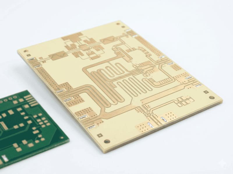
Rogers PCB
- 5 day production timeline
- Premium RO4003C and RO4350B materials
- Specialized for RF and high frequency applications
- Exceptional signal integrity performance
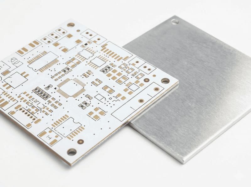
Aluminum PCB
- 1-2 layer designs
- 24 hour rapid production available
- Thickness options: 0.8mm-3.2mm
- Copper weights: 0.5-4oz
- Precision trace/spacing down to 3/3 mil
- Enhanced thermal dissipation
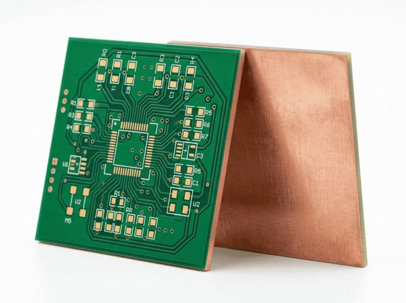
Copper Core PCB
- 1 - 2 layer configurations
- 1.0-2.0mm thickness options
- 1-2oz copper weights
- Superior thermal management properties
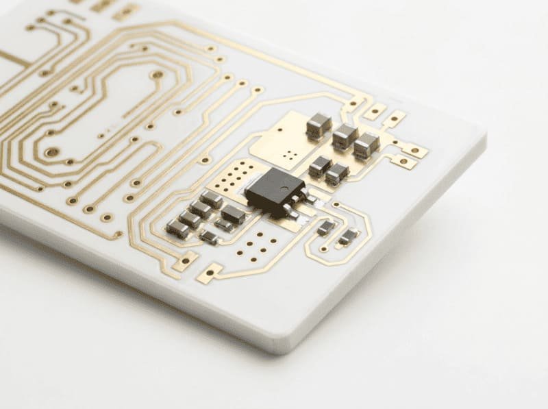
Ceramic PCB
- Layer count: 1-2 layers
- Turn time: from 24 hours
- Thickness: 0.8mm-3.2mm
- Copper: 0.5-4oz
- Min trace/spacing: 3/3 mil
Get Your Turnkey PCB Manufacturing Quote Within 12 Hours
Our experienced engineering team will analyze your requirements and provide a detailed production plan with transparent pricing.
