 Skip to content
 Rogers PCB Manufacturer
The Premium Solution for High Frequency Applications
What is Rogers PCB?
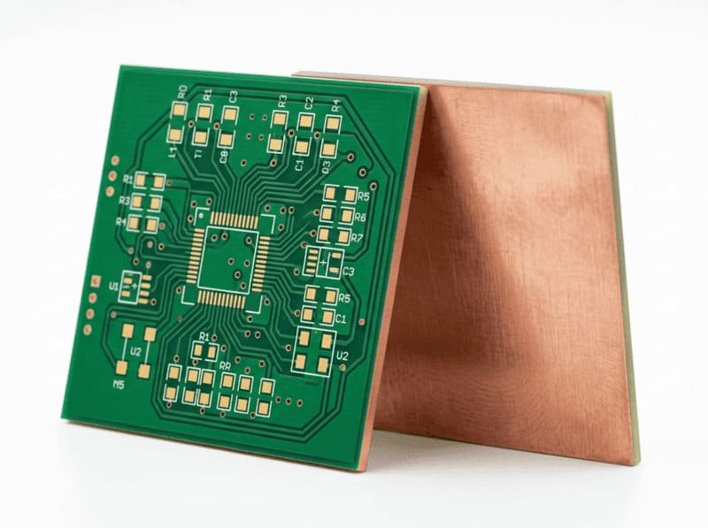
Rogers PCBs are specialized circuit boards manufactured using high performance Rogers Corporation materials specifically designed for radio frequency (RF) and high frequency applications. Unlike standard FR4 boards, Rogers PCBs use advanced materials like RO4003C and RO4350B that maintain consistent electrical properties across wide frequency ranges and environmental conditions. I’ve worked with these materials extensively and can confirm they deliver exceptional performance where standard materials simply can’t compete.
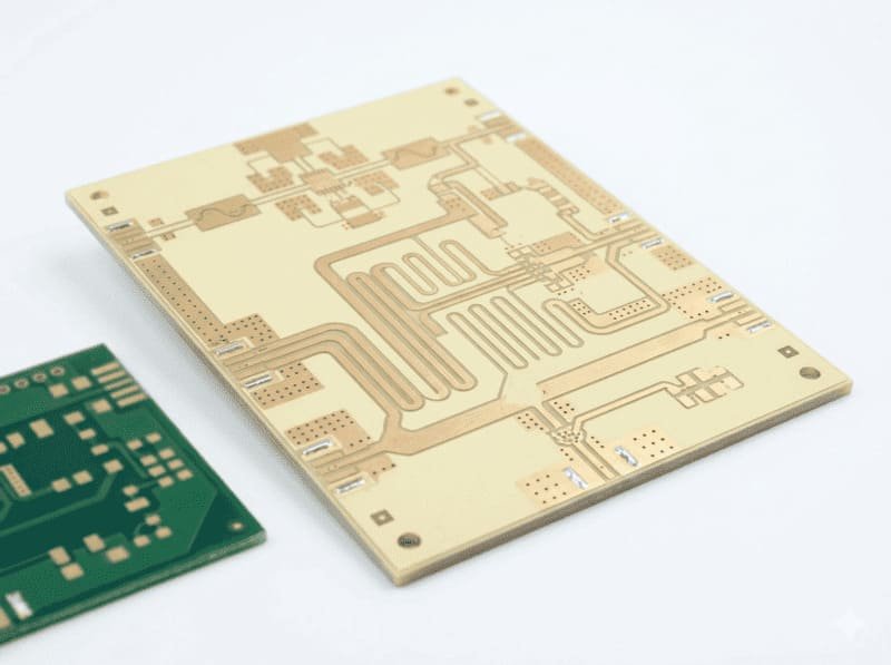
At LZJPCB, our Rogers PCBs feature precisely controlled dielectric constants, low signal loss characteristics, and excellent thermal stability. These properties are critical for applications operating in the GHz frequency range, including wireless communications, radar systems, and industrial sensing equipment. When I work with clients in these demanding fields, Rogers materials are often the only viable solution for maintaining signal integrity at high frequencies while ensuring reliable performance across operating conditions.
What are the advantages of Rogers PCB?
Superior High Frequency Performance
Rogers materials maintain consistent dielectric constants across wide frequency ranges (up to 110 GHz), ensuring predictable electrical performance for critical RF applications. When I tested identical circuit designs on FR4 versus Rogers materials, the Rogers boards showed up to 40% less insertion loss at 10GHz, directly translating to stronger signal transmission and greater range for wireless applications.
The low dissipation factor (typically 0.0025 to 0.0037 at 10GHz) significantly reduces signal loss compared to standard FR4 (0.015 to 0.025), enabling more efficient power transmission in RF circuits. For one industrial client manufacturing remote sensor systems, switching to Rogers materials extended their effective signal range by nearly 30% while using the same power levels.
Exceptional Thermal and Mechanical Stability
Rogers materials feature coefficient of thermal expansion (CTE) values closely matched to copper, minimizing stress during thermal cycling and dramatically reducing the risk of plated through hole failures. I've seen Rogers PCBs maintain perfect operation through thousands of thermal cycles where standard materials would develop micro cracks and connection failures.
The thermal conductivity of Rogers materials (typically 0.6-0.7 W/m/K) exceeds standard FR4 (0.25 W/m/K), providing better heat dissipation for high power RF applications. For industrial automation applications operating in variable temperature environments, this thermal stability ensures consistent performance across the full operating range without signal degradation or mechanical failures.
Consistent Performance in Challenging Environments
Rogers materials maintain stable electrical properties across wide humidity and temperature ranges (-55°C to +125°C for most grades), ensuring reliable operation in industrial and outdoor applications. For equipment deployed in harsh factory environments, this environmental stability translates directly to fewer field failures and longer service life.
The low moisture absorption characteristics (0.02% for RO4350B vs. 0.20% for FR4) prevent significant shifts in electrical properties during humidity changes. I recently worked with a European client whose equipment operates in highly variable conditions across different manufacturing facilities, the Rogers based design eliminated the performance variations they had experienced with standard materials.
What is Rogers PCB commonly used in?
Rogers PCBs are essential components in cellular base stations, providing the low loss signal transmission required for 4G and 5G infrastructure. The precise impedance control and minimal signal degradation over distance allow for optimized antenna feeds and power amplifier circuits. The thermal stability ensures reliable operation despite the significant temperature variations experienced in outdoor installations.
I recently supported a project for industrial wireless communication hubs where Rogers materials were crucial for maintaining network reliability across a large manufacturing campus. The material's consistent performance regardless of seasonal temperature variations eliminated the periodic signal issues they had experienced with standard PCB materials.
Industrial radar sensors for process monitoring and safety applications rely on Rogers PCBs for their precise electrical characteristics at microwave frequencies. The low signal loss enables more accurate measurements and greater detection range compared to standard materials. The stable dielectric constant across temperature ranges ensures measurement consistency regardless of environmental conditions.
For automated manufacturing systems using millimeter wave sensors for precision positioning, Rogers PCBs provide the signal integrity required for accurate measurements down to sub millimeter precision. I've worked with automation engineers who found that only Rogers based circuits could deliver the consistent sensing performance their applications demanded.
As digital communication speeds continue to increase, Rogers materials are becoming essential for advanced industrial control systems where signal integrity at high data rates is critical. The low dielectric loss reduces signal distortion in high speed differential pairs, enabling cleaner signal transmission at data rates exceeding 10 Gbps.
For industrial equipment requiring real time processing of large sensor data streams, Rogers hybrid designs (combining Rogers and FR4 materials in strategic layers) provide the perfect balance of performance and cost effectiveness. The precise signal timing made possible by Rogers materials allows for more accurate synchronization across distributed control systems.

Rogers PCB Design Considerations

Selecting the optimal Rogers material involves balancing electrical requirements, thermal considerations, and cost constraints. For industrial sensing applications below 20 GHz, RO4003C typically provides the best value while meeting performance requirements. Applications above 20 GHz or requiring maximum signal integrity often justify the premium cost of RO4350B or specialized RT/duroid® materials.
When working with industrial automation clients, I first analyze their specific frequency range, operating environment, and performance requirements before recommending a material. For mixed signal designs, we often implement hybrid stackups using Rogers materials only for critical RF layers, significantly optimizing production costs while maintaining essential performance characteristics.
Rogers PCB stackups require careful planning to optimize electrical performance while managing manufacturing complexity and cost. For multilayer designs, we typically recommend Rogers material only for the critical RF layers, with FR4 used for power and digital signal layers. This hybrid approach optimizes both performance and cost.
The critical parameters for stackup planning include:
Maintaining consistent impedance across different material transitions
Minimizing signal crossings between different dielectric materials
Strategic placement of ground planes to isolate RF sections from digital circuits
Controlled thickness tolerances to ensure predictable electrical performance
Our engineering team provides detailed stackup recommendations based on your specific application requirements, optimizing both performance and manufacturability.
Rogers PCBs require precise impedance control, typically maintained within ±7% tolerance compared to ±10% for standard FR4 designs. For critical RF transmission lines, we implement specialized manufacturing processes to achieve impedance tolerances as tight as ±5% when required. Our advanced simulation tools allow us to predict and optimize impedance characteristics before production.
For high frequency applications, trace geometry becomes increasingly critical. We recommend:
Minimizing vias in RF signal paths to reduce discontinuities
Implementing smooth trace corners (45° or curved) rather than 90° bends
Maintaining consistent reference planes beneath RF traces
Carefully controlling copper roughness for minimum insertion loss at high frequencies
These design considerations are especially important for industrial communication systems operating above 5 GHz, where small impedance variations can significantly impact system performance.
Rogers PCB Material
RO4003C - Balanced Performance and Cost

RO4003C offers a dielectric constant of 3.38 (±0.05) with excellent stability across frequency ranges up to 40 GHz, making it ideal for commercial and industrial RF applications. The material provides an excellent balance between performance and cost, with manufacturing processes similar to standard FR4 for efficient production. Its thermal conductivity of 0.71 W/m/K effectively dissipates heat in power amplifier circuits and high power RF applications.
Based on my experience with industrial clients, RO4003C is the most commonly selected Rogers material for applications where cost effectiveness is important but standard FR4 materials can’t meet the electrical performance requirements. It’s particularly well suited for industrial sensing equipment operating in the 5-10 GHz range where signal integrity is critical.
RO4350B - Premium Performance
RO4350B features a higher dielectric constant of 3.48 (±0.05) and superior thermal performance, recommended for the most demanding RF and microwave applications up to 50 GHz. The material provides exceptional electrical stability across wide temperature ranges, critical for outdoor and industrial applications experiencing significant environmental variations. Its outstanding thermal resistance (Tg>280°C) makes it ideal for lead free assembly processes and high temperature operating environments.
I typically recommend RO4350B for clients developing industrial equipment that must maintain precise RF characteristics in harsh environments or applications where absolute minimum signal loss is essential for system performance. The material’s premium characteristics justify the higher cost in applications where reliability is paramount.

RT/duroid® 5880 - Ultra Low Loss Performance

RT/duroid® 5880 delivers an extremely low dielectric constant of 2.2 (±0.02) and the lowest loss tangent (0.0009 at 10 GHz) in the Rogers lineup, ideal for millimeter wave applications above 50 GHz. The material features PTFE (polytetrafluoroethylene) reinforced with glass microfibers, providing exceptional electrical properties for the most demanding RF applications. Its unique composition offers the lowest moisture absorption (0.02%) of any Rogers material, ensuring stable performance in variable humidity environments.
For specialized industrial applications requiring maximum signal transmission efficiency, particularly in millimeter wave systems operating above 60 GHz, I’ve found RT/duroid® 5880 to be the only material that can deliver the necessary performance. While significantly more expensive than other options, its exceptional electrical properties make it indispensable for cutting edge high frequency designs.
RO3000 Series - High Frequency Ceramic Filled PTFE
The RO3000 series materials combine ceramic filled PTFE for stable electrical properties at frequencies exceeding 77 GHz, ideal for advanced radar and millimeter wave applications. These premium materials offer extremely tight tolerance on dielectric constant (±0.04 for RO3003), critical for phase sensitive array applications. The series provides exceptional dimensional stability during processing, minimizing registration issues in multilayer constructions.
These specialized materials are primarily recommended for the most demanding RF applications where absolute performance is required regardless of cost. In the industrial automation sector, I’ve seen them used primarily in advanced radar based systems for precision measurement and detection applications where sub millimeter accuracy is essential.

LZJPCB Rogers PCB Manufacturing Capabilities
| Features | Capabilities |
|---|---|
| Rogers Materials Available | RO4003C, RO4350B, RO3003, RO3006, RO3010, RT/duroid® 5870/5880, TMM® series |
| Layer Count | Up to 20 layers (Rogers/FR4 hybrid), up to 8 layers (all-Rogers construction) |
| Board Thickness | 0.2mm to 3.2mm |
| Minimum Trace/Space | 3/3 mil (0.076mm) standard, down to 2/2 mil (0.051mm) for advanced designs |
| Surface Finish Options | ENIG, Immersion Silver, Immersion Tin, Hard Gold, Silver/Gold hybrid for RF applications |
| Minimum Hole Size | 0.2mm mechanical drilling, 0.1mm laser drilling for blind vias |
| Hybrid Construction | Specialized capabilities for mixed Rogers/FR4 construction |
| Impedance Control | ±7% standard, ±5% available for critical applications |
| Typical RF Frequencies | Optimized designs for 1-77 GHz applications |
| Assembly Options | Lead-free assembly with controlled thermal profiles for Rogers materials |
| RF Testing | Specialized testing available for impedance verification at microwave frequencies |
| Quality Testing | 100% electrical testing, AOI inspection, cross-section analysis |
| Typical Lead Times | Prototype: 5 days, Standard Production: 7-10 days, Volume Production: 15 days |
| Special Features | Embedded passive components, Rogers/FR4 hybrid designs, selective plating |
Why Choose LZJPCB for Rogers PCB?
Specialized RF Engineering Expertise
Our RF engineering team brings over 25 years of combined experience with high frequency circuit design and manufacturing. We don't just fabricate your Rogers PCB designs, we provide expert consultation throughout the process to optimize performance and manufacturability. For every Rogers project, we conduct comprehensive design reviews focused specifically on RF performance considerations that might be overlooked by general PCB manufacturers.
I've personally worked with dozens of industrial clients to optimize their RF designs, identifying potential issues like impedance discontinuities, signal reflections, and crosstalk problems before they impact production. Our specialized design guidance has helped many clients achieve first pass success with complex RF designs where previous attempts with standard PCB manufacturers had failed to meet performance requirements.
Advanced Manufacturing Infrastructure
LZJPCB has invested in dedicated Rogers material processing equipment not found at standard PCB manufacturers. Our specialized drilling systems maintain precise hole quality in the challenging ceramic filled and PTFE based materials, while our advanced lamination presses implement material specific pressure and temperature profiles optimized for Rogers composites.
Our manufacturing facilities maintain strict environmental controls for temperature, humidity, and contamination prevention, essential for consistent results with premium RF materials. For industrial clients with demanding applications, we implement comprehensive traceability systems that document every aspect of the manufacturing process, from raw material verification through final electrical testing.
Proven Success with Industrial RF Applications
Our portfolio includes successful Rogers PCB projects for leading industrial automation and communication equipment manufacturers worldwide. We've helped clients overcome challenging RF design issues including:
- Optimizing radar sensor performance for increased detection range
- Implementing reliable industrial wireless networks in harsh factory environments
- Developing high speed data acquisition systems with minimal signal degradation
- Creating reliable outdoor communication equipment resistant to environmental variation
Working with industrial clients across Europe, Asia, and North America has given us deep insight into the specific requirements of industrial RF systems. We understand the importance of reliable performance in challenging environments where equipment must operate continuously for years with minimal maintenance.
Rogers PCB FAQ
How do I determine which Rogers material is best for my application?
Selecting the optimal Rogers material depends on several key factors:
**Frequency range**: For applications below 20 GHz, RO4003C typically provides the best balance of performance and cost. Applications from 20-50 GHz often require RO4350B, while frequencies above 50 GHz may need specialized RT/duroid® materials.
**Environmental conditions**: If your equipment operates in highly variable temperatures or humidity, materials like RO4350B provide superior stability across environmental changes.
**Power handling requirements**: Applications with high RF power levels benefit from materials with better thermal conductivity like RO4350B (0.69 W/m/K) compared to RT/duroid® 5880 (0.50 W/m/K).
**Cost sensitivity**: RO4003C offers the most cost effective solution for many applications, with manufacturing processes similar to standard FR4.
Our engineering team provides material selection guidance based on your specific application requirements, often recommending hybrid approaches that use Rogers materials only where absolutely necessary to optimize both performance and cost.
What are the cost implications of using Rogers materials?
Rogers materials typically cost 3-10 times more than standard FR4 depending on the specific material grade, thickness, and copper weight. However, several factors should be considered in the total cost analysis:
**Hybrid construction options**: Using Rogers material only for critical RF layers while implementing FR4 for power and digital signals can reduce material costs by 40-60% compared to all Rogers designs.
**Performance benefits**: The superior electrical performance often allows for more compact designs and fewer signal amplification stages, potentially reducing overall system costs.
**Reliability improvements**: The enhanced stability and reduced failure rate in harsh environments can significantly lower lifetime costs through reduced maintenance and replacement needs.
For production efficiency, we recommend standardizing on specific Rogers material types and thicknesses across projects when possible, as this allows for more efficient material utilization and potential volume pricing benefits.
How does the manufacturing process differ for Rogers PCBs?
Rogers PCB manufacturing requires several specialized processes compared to standard FR4 production:
**Drilling modifications**: Rogers materials require precisely controlled drill speeds, feeds, and entry/exit materials to prevent smearing and ensure clean hole walls. Our drilling parameters are optimized for each specific Rogers material type.
**Specialized lamination cycles**: The thermal and pressure profiles must be carefully controlled to account for the unique properties of Rogers materials, particularly in hybrid constructions combining different material types.
**Modified plating processes**: Through hole plating requires adjusted chemical processes and cycle times for optimal adhesion to Rogers materials.
**Enhanced handling precautions**: Many Rogers materials are more susceptible to handling damage and contamination, requiring specialized training for production personnel and modified handling procedures throughout the manufacturing process.
These specialized processes contribute to the higher cost of Rogers PCBs but are essential for achieving the performance and reliability benefits these premium materials offer.
Can Rogers materials be combined with standard FR4 in the same board?
Yes, hybrid constructions combining Rogers and FR4 materials in the same PCB are common and often represent the most cost effective approach. This technique places Rogers materials only in layers requiring superior RF performance while using standard FR4 for power, ground, and digital signal layers.
Key considerations for successful hybrid designs include:
**Symmetrical construction**: Maintaining material balance around the center of the stackup to prevent warping during thermal processes.
**Controlled impedance transitions**: Carefully designing transitions between Rogers and FR4 sections to maintain signal integrity.
**Modified lamination cycles**: Specialized pressure and tempera
ture profiles to account for the different material characteristics during bonding.
Our engineering team provides detailed stackup recommendations for hybrid designs, optimizing both performance and manufacturability while minimizing production costs.
What surface finishes are recommended for Rogers PCBs?
The optimal surface finish for Rogers PCBs depends on your specific application requirements:
**ENIG (Electroless Nickel Immersion Gold)**: Provides excellent solderability and contact reliability with minimal impact on RF performance. This is our most commonly recommended finish for Rogers PCBs in industrial applications.
**Immersion Silver**: Offers slightly better RF performance than ENIG due to lower insertion loss, but with somewhat reduced shelf life and potential tarnishing concerns.
**Hard Gold**: Recommended for RF switches and applications requiring frequent connection/disconnection cycles or exceptional wear resistance.
**Selective plating**: For optimal RF performance, we can apply different surface finishes to different areas of the board for example, ENIG for component mounting areas and silver or hard gold for critical RF transmission lines.
Our engineers can provide specific finish recommendations based on your application’s frequency range, environmental exposure, and assembly requirements.
What testing methods ensure Rogers PCB quality?
LZJPCB implements comprehensive testing protocols specifically developed for Rogers PCBs:
**Specialized electrical testing**: Beyond standard continuity testing, we offer impedance verification at RF frequencies for critical transmission lines.
**Microsection analysis**: Cross sectional examination verifies plated through hole quality, layer to layer registration, and material integrity.
**X-ray inspection**: Identifies potential voids or registration issues in multilayer constructions.
**Dedicated RF visual inspection**: Specialized inspection under magnification for RF trace quality and signal path integrity.
**Environmental stress testing**: For critical applications, we can perform thermal cycling tests to verify reliability under temperature stress.
For industrial clients with mission critical applications, we can implement customized testing protocols specific to your operating environment and reliability requirements. Our quality assurance processes are fully documented with comprehensive test reports available upon request.
Unlock More Possibilities with LZJPCB Solutions
From standard rigid PCBs to advanced specialized technologies, our manufacturing services deliver exceptional quality across diverse applications and industries.
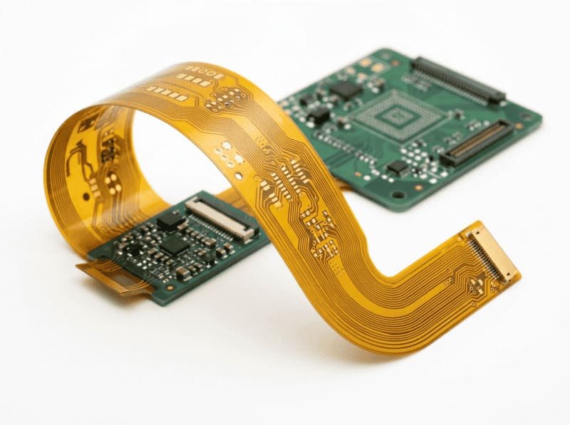
Flex PCB
- Layer count: 1-32 layers
- Turn time: from 24 hours
- Thickness: 0.4mm-4.0mm
- Copper: 1-15oz
- Min trace/spacing: 3/3 mil
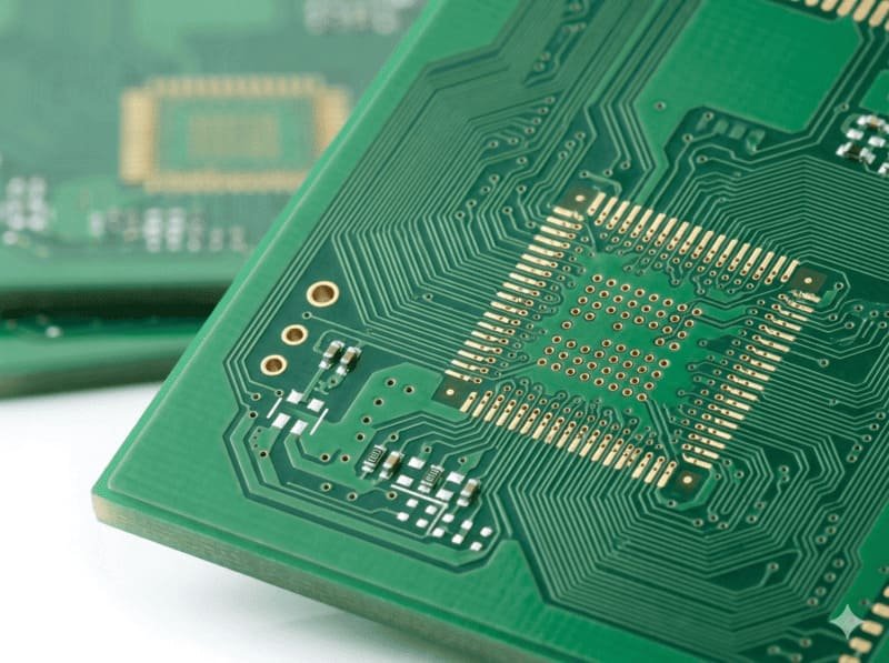
HDI PCB
- 4-20 layer HDI designs
- Advanced buried and blind via technology
- 10 day production timeline
- Ideal for complex, space constrained applications
Rogers PCB
- 5 day production timeline
- Premium RO4003C and RO4350B materials
- Specialized for RF and high frequency applications
- Exceptional signal integrity performance
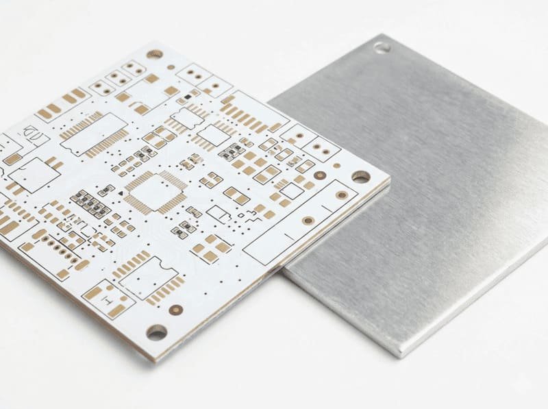
Aluminum PCB
- 1-2 layer designs
- 24 hour rapid production available
- Thickness options: 0.8mm-3.2mm
- Copper weights: 0.5-4oz
- Precision trace/spacing down to 3/3 mil
- Enhanced thermal dissipation
Copper Core PCB
- 1 - 2 layer configurations
- 1.0-2.0mm thickness options
- 1-2oz copper weights
- Superior thermal management properties
Ceramic PCB
- Layer count: 1-2 layers
- Turn time: from 24 hours
- Thickness: 0.8mm-3.2mm
- Copper: 0.5-4oz
- Min trace/spacing: 3/3 mil
Get Your Turnkey PCB Manufacturing Quote Within 12 Hours
Our experienced engineering team will analyze your requirements and provide a detailed production plan with transparent pricing.
