 Skip to content
 PCB assembly defects can transform a perfectly designed circuit into an expensive paperweight. Despite careful planning, many engineers receive assembled boards that fail testing, causing project delays and budget overruns that could have been avoided with proper defect awareness.
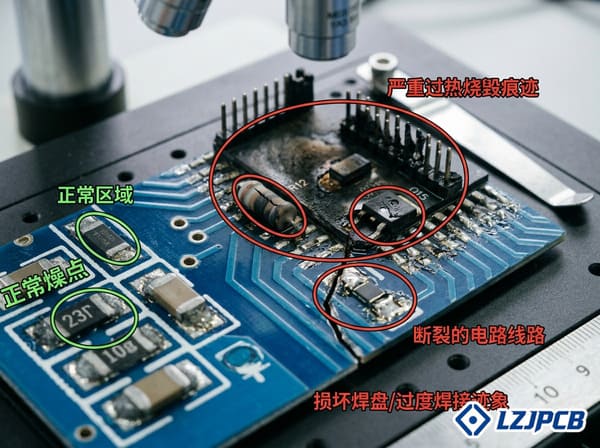
PCB assembly defects include solder issues (bridges, insufficient solder, cold joints), component problems (misalignment, tombstoning, wrong polarity), board damage (pad lifting, trace damage), and hidden defects requiring specialized inspection. These issues arise from process control failures during PCB assembly.

Understanding PCB assembly defects is crucial for both designers and manufacturers. At LZJPCB, I’ve analyzed thousands of failed boards to identify defect patterns and develop prevention strategies. The most frustrating aspect of assembly defects is that many are entirely preventable through proper design practices, process controls, and quality inspection. Recognizing these common defects helps you communicate effectively with your manufacturer and implement design choices that minimize their occurrence.
Why Do PCB Boards Fail?
PCB failures can bring production lines to a halt and delay product launches. Many engineers struggle to identify the root causes, leading to repeated failures and mounting frustration as deadlines slip and costs increase.
PCB boards fail due to design flaws (inadequate thermal management, signal integrity issues), manufacturing defects (improper copper etching, drill misalignment), assembly problems (poor soldering, component damage), material failures (delamination, conductive anodic filament formation), and operational stress (thermal cycling, vibration, humidity).
PCB failure analysis is a critical part of my work at LZJPCB. I’ve investigated countless board failures across different industries and applications. What’s fascinating is how often these failures follow predictable patterns that could have been prevented with proper design choices and manufacturing controls. Understanding why boards fail gives you the knowledge to design more reliable products and choose manufacturing partners who prioritize quality.
Common Causes of PCB Failure
PCB failures stem from multiple sources throughout the design, manufacturing, and usage lifecycle. My experience troubleshooting failed boards has shown that understanding these failure modes helps prevent their recurrence in future designs.
| Failure Category | Common Issues | Root Causes | Prevention Strategies |
|---|---|---|---|
| Design-Related Failures | Signal integrity problems, thermal issues, EMI/EMC issues | Inadequate clearances, improper stackup, poor component placement | DFM review1, simulation, thermal modeling |
| Material Failures | Delamination, CAF formation, substrate breakdown | Poor material selection, moisture exposure, manufacturing defects2 | Quality materials, proper storage, moisture management |
| Manufacturing Defects | Etching problems, drill misalignment, plating voids | Process control issues, equipment problems, improper parameters | Vendor qualification, inspection protocols |
| Assembly Problems | Solder defects, component damage, misalignment | Process control failures, equipment calibration, operator error | Process validation, automated inspection, quality controls |
| Environmental Stress | Thermal cycling failure, vibration damage, corrosion | Operating environment beyond design parameters, inadequate protection | Environmental testing, conformal coating, proper enclosure |
| Electrical Overstress | Burnt traces, component failure, dielectric breakdown | Voltage spikes, current surges, static discharge | Protection circuits, proper grounding, ESD controls |
Design related failures account for approximately 50% of the PCB failures I investigate. Even the best manufacturing process can’t compensate for fundamental design issues. Common design problems include inadequate trace widths for current requirements, insufficient clearance between high voltage nets, improper thermal management3 for heat-generating components, and signal integrity issues4 from poor routing or stackup design.
I recently analyzed a failed industrial controller board that exhibited intermittent operation. The root cause was a digital signal routed directly parallel to a high current motor driver trace without adequate separation or ground planes. During motor activation, the resulting electromagnetic interference corrupted the digital signal. This design flaw could have been identified through proper EMI/EMC analysis5 before production.
Material failures often manifest as delamination (separation of PCB layers) or CAF (Conductive Anodic Filament) formation. These issues frequently result from moisture absorption during storage or manufacturing. At LZJPCB, we maintain strict humidity control and bake PCBs before assembly when needed to prevent these failures. Material selection is equally important, using lower grade FR4 in high temperature applications inevitably leads to premature failure.
Manufacturing defects in the bare PCB include etching problems (over etching or under etching), drill misalignment, and plating voids in holes. These issues can create intermittent connections that are particularly difficult to troubleshoot. Proper PCB fabrication vendor qualification and incoming inspection are key to preventing these defects from reaching assembly.
Assembly related failures include the numerous soldering defects discussed earlier, component damage from excessive heat or ESD, and misalignment issues. Modern assembly equipment has significantly reduced these problems, but they still occur, particularly with complex boards or challenging component packages like fine pitch BGAs and QFNs.
Environmental stresses cause PCB failure when boards operate outside their design parameters. Thermal cycling (repeated heating and cooling) is particularly damaging, causing solder joint fatigue and eventual failure. I’ve seen this frequently in automotive applications where temperature variations are extreme. Vibration similarly stresses solder joints and component attachments, while humidity can cause corrosion and electrical leakage between traces.
Electrical overstress failures occur when circuits experience voltage or current beyond their design limits. This might happen during power surges, ESD events, or when connected to incompatible equipment. The resulting damage often appears as burnt traces, failed components, or carbonized board material. Protection circuits and proper grounding can prevent many of these failures.
One pattern I’ve observed is that failures rarely have a single cause. More often, there’s a combination of minor issues that collectively lead to failure. For example, a slightly substandard solder joint might function perfectly in a controlled environment but fail quickly when subjected to vibration. This complexity makes comprehensive testing under realistic conditions crucial for critical applications.
Can a PCB Be Repaired?
When faced with PCB failures, especially in low volume or prototype runs, the decision to repair versus replace can have significant timeline and cost implications. Many engineers lack experience with PCB repair6 and may discard boards that could be salvaged.
PCBs can often be repaired by replacing damaged components, resoldering joints, rebuilding damaged pads, or jumping broken traces. Repair success depends on the defect type, board complexity, available tools, technician skill level, and economic factors. Simple solder defects are easily fixed while multilayer board internal damage is usually irreparable.
PCB repair6 has been an important part of our service offering at LZJPCB. We frequently help clients salvage expensive prototypes or low-volume production runs when defects occur. The repair decision involves both technical feasibility and economic considerations. I’ve developed a systematic approach to evaluating repairability7 that helps make this decision process more objective and reliable.
PCB Repair: Feasibility, Techniques and Limitations
PCB repair6 requires specialized tools, techniques, and experience. Through hundreds of repair projects, I’ve developed guidelines for determining when repair is feasible and which approaches are most effective for different defect types.
| Defect Type | Repairability | Repair Techniques | Tools Required | Success Rate |
|---|---|---|---|---|
| Solder Bridges | Highly repairable | Solder wick, hot air rework | Soldering iron, hot air station, flux | 95%+ |
| Insufficient Solder | Highly repairable | Adding solder, reflowing | Soldering iron, flux, solder | 90%+ |
| Component Misalignment | Moderately repairable | Component removal and replacement | Hot air station, soldering iron, tweezers | 80-90% |
| Lifted Pads | Moderately repairable | Scraping traces, jumper wires | Micro knife, fine wire, epoxy, soldering iron | 70-80% |
| Broken Traces | Moderately repairable | Jumper wires, conductive ink | Fine wire, micro knife, conductive pen | 80-90% |
| Damaged Plated Holes | Limited repairability7 | Eyelets, wire jumpers | Eyelet tools, drill, wire | 50-70% |
| Delamination | Rarely repairable | Board replacement typically required | N/A | <20% |
| Internal Layer Damage | Rarely repairable | Board replacement typically required | N/A | <10% |
| BGA Connection Failure | Moderately repairable | BGA reball and replacement | BGA rework8 station, stencils, preforms | 60-80% |
| Burnt/Charred Board | Rarely repairable | Board replacement typically required | N/A | <20% |
Solder defects are the most common and fortunately the most repairable PCB assembly issues. Simple problems like solder bridges can be fixed with a soldering iron, flux, and solder wick with nearly 100% success. Insufficient solder joints can be reinforced by adding solder and reflowing. These repairs are fast, economical, and highly reliable when performed by skilled technicians.
Component level repairs involve removing and replacing damaged or incorrectly placed parts. Surface mount components can be removed using hot air rework stations, while through hole components require solder suction tools to clear holes before replacement. The success rate depends heavily on pad condition after component removal, excessive heat or force during removal can damage pads and complicate repairs.
I recently supervised the repair of a prototype medical device9 controller where several QFN components were mounted with incorrect orientation. Using a hot air rework station with precisely controlled temperature profiles, we successfully removed the components without damaging the pads, cleaned the sites, and replaced the components correctly. This saved our client several thousand dollars in replacement costs and weeks of waiting for new boards.
Pad and trace repairs are more challenging but often successful. For lifted or damaged pads, the technique involves carefully scraping back the solder mask to expose additional trace area, then creating a new solder point. For broken traces10, thin jumper wires can bridge the gap. We sometimes use conductive epoxy or specialized conductive pens for delicate repairs. These repairs require microscopic work and steady hands but can restore full functionality.
Board level damage such as delamination, internal layer breaks, or burnt/charred areas generally cannot be repaired reliably. When we encounter these issues, we typically recommend replacement rather than repair. The exception might be prototype or extremely expensive boards where a partial repair might allow limited functionality for testing purposes.
BGA (Ball Grid Array) repairs present special challenges since the connections are hidden beneath the component. Specialized BGA rework8 stations are required, along with X-ray inspection to verify proper connection. At LZJPCB, we achieve about 70-80% success rates with BGA repairs, though this depends greatly on board condition and component type.
The economic calculation for repair versus replacement considers several factors:
- Board replacement cost and lead time
- Repair time and materials cost
- Confidence level in repair durability
- Critical path impact on overall project
- Available repair expertise and equipment
For prototype or low volume production, repair is often economically advantageous even with moderate success probability. For high volume production, the calculation shifts toward replacement unless the defect is simple and repair success rates are very high.
Is It Worth Replacing a PCB Board?
When electronic devices fail, the PCB replacement11 question triggers difficult cost benefit analysis. Without clear guidelines, many make expensive mistakes—either replacing PCBs unnecessarily or wasting time trying to repair boards that should be replaced.
PCB replacement is worth considering when: repair costs exceed 50-70% of replacement cost, the board has multiple or severe defects, internal layers are damaged, specialized repair equipment is unavailable, reliability requirements are high, or when time constraints favor replacement. Consumer products often warrant replacement while industrial equipment may justify repair.
This question comes up frequently in both manufacturing and field service contexts. At LZJPCB, we advise clients on this decision regularly, weighing technical, economic, and practical factors. The right answer varies significantly based on the specific situation, but I’ve developed a framework that helps guide this decision process more objectively.
Evaluating PCB Replacement: A Decision Framework
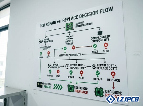
The replacement versus repair decision involves multiple considerations beyond simple cost comparison. Based on hundreds of such decisions, I’ve identified the key factors that should inform this choice.
| Consideration Factor | Favors Repair | Favors Replacement |
|---|---|---|
| Economic Factors | Repair cost <50% of replacement | Repair cost >70% of replacement |
| Damage Severity | Surface level defects only | Internal layer damage, multiple defects12 |
| Availability | Long lead time for new PCBs | New PCBs readily available |
| Equipment Value | High value equipment (>$1000) | Low value consumer products (<$100) |
| Time Constraints | Immediate functionality needed | Can wait for replacement |
| Reliability Requirements | Temporary function acceptable | Long term reliability critical |
| Repair Resources | Skilled technicians available | Limited repair capabilities |
| Obsolescence | Board no longer manufactured | Current production board |
| Documentation | Schematics and BOMs available | Limited technical information |
| Regulatory Considerations | Non critical applications | Medical, aerospace, safety applications |
Economic factors usually drive the initial consideration. As a general rule, if repair costs13 exceed 70% of replacement costs, replacement is typically the better option. However, this calculation must include all associated costs. For an industrial controller board, for instance, replacement might involve not just the board cost but also reconfiguration, calibration, and system downtime. In such cases, repair might be justified even at 80-90% of replacement cost.
Damage severity is a key technical consideration. Surface level defects like solder issues or damaged components can usually be repaired reliably. However, internal layer damage in multilayer boards, extensive charring from electrical failures, or multiple defect areas generally favor replacement. I recently assessed a power supply board with visible delamination and charring near voltage regulators; replacement was the clear choice as repair would have been unreliable.
Availability sometimes forces the decision regardless of other factors. When replacement boards have extremely long lead times—as has been common during recent supply chain disruptions—even challenging repairs might be justified. Conversely, if replacement boards are readily available at reasonable cost, the repair threshold tends to lower.
Equipment value and purpose strongly influence the decision. For expensive industrial equipment, medical devices, or specialized systems, repair is more frequently justified. The board in a $100,000 industrial machine might warrant a $2,000 repair effort, while a similar board in a $200 consumer device would not. This calculation considers not just the board cost but the overall system value and downtime implications.
Time constraints often become the deciding factor in production environments. A manufacturer facing production line downtime might opt for the fastest solution regardless of cost. I’ve seen cases where clients air freight replacement boards at premium prices rather than attempt repairs that would take longer, even when repair would be less expensive in pure component costs.
Reliability requirements vary by application. Temporary repairs might be acceptable for non critical systems to restore basic functionality while waiting for replacements. However, safety critical systems, medical devices, aerospace applications, or other high reliability contexts generally favor replacement over repair unless the repair can be validated to the same standards as new production.
Available repair resources matter significantly. Even technically feasible repairs require proper equipment and expertise. Organizations without microscopic soldering capabilities, BGA rework stations, or experienced technicians will have lower repair success rates, shifting the equation toward replacement. At LZJPCB, we have specialized repair stations and trained technicians, allowing us to successfully repair boards that might be considered unrepairable in general maintenance settings.
Obsolescence considerations often arise with older equipment. When boards are no longer manufactured, repair becomes more attractive even if challenging. I’ve worked with clients operating legacy industrial equipment where replacement boards simply weren’t available, making repair the only viable option regardless of condition.
Documentation availability impacts repair feasibility. With complete schematics, BOMs, and design files, even complex repairs become more feasible. Without documentation, troubleshooting becomes more difficult and repair success rates decline. This is particularly relevant for proprietary or older equipment where documentation may be limited.
Regulatory considerations create additional complexity for medical, aerospace, automotive safety systems, and other regulated applications. Repairs to such systems must meet the same validation requirements as original manufacturing. This often makes replacement more practical unless the repair facility has appropriate quality systems and documentation capabilities.
From a sustainability perspective14, repair is generally preferable when technically feasible. Electronic waste is a growing environmental concern, and extending product lifecycles through repair reduces environmental impact. Some of our clients specifically prioritize repair options as part of their sustainability initiatives, accepting somewhat higher costs to reduce electronic waste.
Conclusion
PCB assembly defects include soldering problems, component misplacements, and board damage that can cause circuit failure. While many defects can be repaired through resoldering, component replacement, or trace repair, some damage requires board replacement. The decision between repair and replacement depends on defect severity, cost factors, time constraints, and reliability requirements for the specific application.
-
A DFM review can significantly reduce the risk of design related failures. ↩
-
Learn about manufacturing defects to ensure quality control in your PCB production process. ↩
-
Effective thermal management is crucial for PCB longevity and performance. ↩
-
Understanding signal integrity is key to ensuring reliable PCB operation. ↩
-
EMI/EMC analysis helps prevent interference issues that can compromise PCB functionality. ↩
-
Explore this link to learn effective PCB repair techniques that can save costs and extend the life of your boards. ↩ ↩ ↩
-
This link offers guidelines on assessing PCB repairability, crucial for making informed decisions. ↩ ↩
-
Understand the BGA rework process to tackle complex repairs involving hidden connections. ↩ ↩
-
Explore the unique challenges of repairing prototype medical devices and how to overcome them. ↩
-
Explore effective methods for fixing broken traces to restore PCB functionality. ↩
-
Explore the advantages of PCB replacement to make informed decisions about your electronic devices. ↩
-
Learn how multiple defects can affect the performance and reliability of PCBs. ↩
-
Understanding repair costs is crucial for making cost effective decisions regarding PCB maintenance. ↩
-
Learn how repairing PCBs can reduce electronic waste and promote sustainability. ↩


