Skip to content
The best high-frequency PCB materials for RF applications are low-loss laminates with a dissipation factor (Df) below 0.005 and a stable dielectric constant (Dk). For 2026, here are the top 8 materials I recommend, ranked by use case:
- Rogers RT-duroid 5880 — Df ≈ 0.0009 at 10 GHz. The gold standard for space and military mmWave work.
- Rogers RO3003 — Df ≈ 0.0010. Best for automotive radar at 77/79 GHz.
- Rogers RO4350B — Df ≈ 0.0037. A cost-optimized hydrocarbon ceramic for sub-6 GHz 5G and Wi-Fi.
- Rogers RO4003C — Df ≈ 0.0027. An original RF workhorse for base stations and antennas.
- Panasonic Megtron 6/7/8 — Df ≈ 0.001–0.004. Top-tier high-speed digital and RF, easy to process.
- Astra MT77 — Low-loss laminates for wideband RF and high-speed links.
- Isola FR408HR — A mid-loss laminate characterized to 10 GHz. Great value up to 6 GHz.
- Low-loss advanced FR4 — For short-reach digital links and sub-1 GHz work where cost rules.
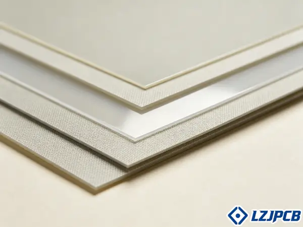
I have run more than 300 PCB projects across 20 countries. I have seen the wrong material sink a whole radar front-end. Let me show you how to pick the right one.
What Makes a PCB Material Suitable for RF Applications
You pick a material by its datasheet numbers, not its brand name. Get Dk and Df wrong, and your RF signal loses power before it ever reaches the antenna.
A PCB material is suitable for RF applications when it has a low dissipation factor (Df), a stable dielectric constant (Dk), and good thermal control. Low Df cuts signal loss. Stable Dk holds impedance steady across frequency. Together they keep the RF signal clean.
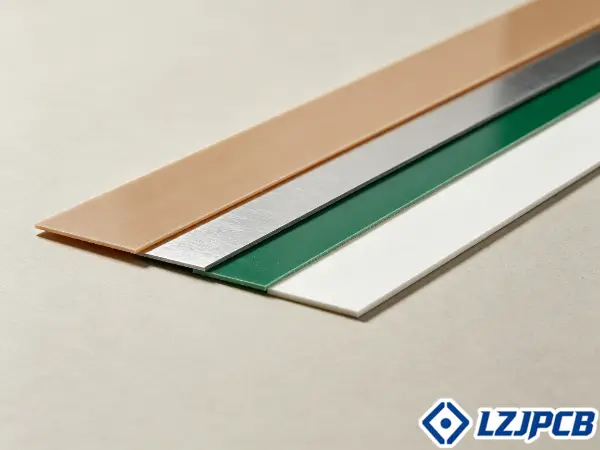
Let me break down the two numbers that matter most, and then show you why the world’s most common board material breaks down at high frequency.
Why FR4 Fails in RF Applications
FR4 fails in RF applications because its Dk shifts with frequency and its Df is too high. Its Dk sits between 4.3 and 4.7 at 1 GHz. Its Df runs near 0.02. That loss is far too high for clean RF work.
The bigger problem is stability. FR4’s Dk drifts 4% from 1 GHz to 10 GHz. It also shifts with heat and humidity. Specialty RF materials hold Dk within ±0.02 to ±0.05. That tight window is what resonant circuits and phased arrays need.
Here is where FR4 breaks down and where it still works:
- Above 1 GHz for RF: FR4 becomes unreliable. High Dk and high Df slow the signal and eat its power.
- Below 500 MHz: FR4 is fine. Its limits do not hurt performance at low frequency.
- 1–5 GHz digital: FR4 still works if traces stay short and the board stays small.
- Impedance control: FR4 holds only ±10–15% tolerance. A tight 50Ω or 100Ω line needs ±5–8%. That gap pushes you to Rogers or similar.
One more note. FR4 is not one product. Standard FR4 has a Tg of 130°C to 180°C by grade. It degrades above 300°C. It survives 260°C reflow for short spells. It is still the base for over 80% of all PCBs made worldwide. But for true RF, its physics run out fast.
Dk and Df Performance Benchmarks for RF Materials
Numbers decide the winner here, not opinions. If you cannot read the Dk and Df benchmarks, you cannot compare two RF materials fairly.
RF-grade materials show Df below 0.005 at 10 GHz, while standard FR4 sits between 0.015 and 0.025. The best PTFE laminates reach Df as low as 0.0009. Dk values range from 2.1 for PTFE up to 10.2 for high-Dk ceramics. Lower Df means less signal lost as heat.
Df is the number that separates an RF laminate from general FR4. Below 0.002 at 10 GHz is low-loss. Between 0.004 and 0.010 is mid-loss. FR4 falls far outside both. Let me put the top materials side by side.
8 Materials Comparison Table
This table lists the eight materials I quote most for RF work. It shows Dk, Df at 10 GHz, and the best use for each. I use these numbers when I help a client pick a stackup.
| Material | Dk | Df @ 10 GHz | Best Use |
|---|---|---|---|
| Rogers RT-duroid 5880 | 2.20 | ~0.0009 | High-Q filters, mmWave phased arrays, space-grade |
| Rogers RO3003 | 3.00 | ~0.0010 | Automotive radar 77/79 GHz, satellite comms |
| Rogers RO3035 | 3.50 | ~0.0015 | Low-loss designs at set impedance targets |
| Rogers RO4003C | 3.38 | ~0.0027 | Base stations, antennas, original RF workhorse |
| Rogers RO4350B | 3.48 | ~0.0037 | Sub-6 GHz 5G, Wi-Fi, IoT, cost-optimized RF |
| Rogers RO3010 | 10.2 | low | Size-constrained designs, smaller passives |
| Panasonic Megtron 6/7/8 | varies | ~0.001–0.004 | High-speed digital, RF, easy to process |
| Isola FR408HR | ~3.6 | mid-loss | PCB antennas to 6 GHz, mid-tier RF |
A few points I want you to notice. RO4350B and RO4003C are hydrocarbon ceramic laminates. They run on standard FR4 lines. No special gear needed. That is why I quote them most.
Rogers RT-duroid 5880 is PTFE. Its Df of 0.0009 is among the lowest of any laminate you can buy. But it needs sodium or plasma treatment before plating. That adds cost and time.
RO3010 breaks the pattern. Its Dk of 10.2 is high on purpose. High Dk shrinks the circuit and cuts wavelength. You pick it when size beats speed.
Thermal and Mechanical Requirements for RF Material Selection
Your board does not just carry a signal. It carries heat and stress too. Ignore the thermal side and your vias crack during the first reflow cycle.
RF material selection must check Tg, Td, CTE, and thermal conductivity, not just Dk and Df. Rogers materials reach a Tg near 280°C against FR4’s 130–180°C. Their Z-axis CTE sits near 25 ppm/°C against FR4’s 70 ppm/°C. Lower CTE means fewer cracked vias.
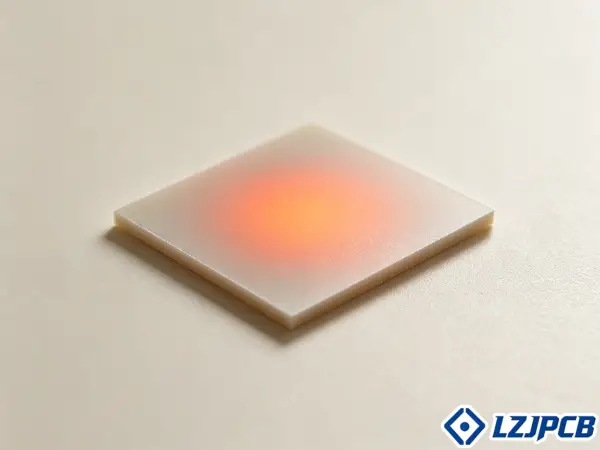
I have seen good boards fail from heat alone. Here is what I check on every RF stackup, and why each number matters for the life of your board.
Thermal properties to check:
- Glass transition temperature (Tg): The point where the resin softens. Rogers near 280°C survives lead-free reflow at 250°C with margin. Low Tg risks cracked vias and lifted pads.
- Decomposition temperature (Td): Where the material breaks down chemically. Rogers RO4000 exceeds 390°C. This is separate from Tg. A high Tg does not mean a high Td.
- CTE (X, Y, Z axes): FR4’s X-Y CTE of 16 ppm/°C matches copper’s 17 ppm/°C well. The danger is the Z-axis. FR4’s 70 ppm/°C strains via barrels during thermal cycles. Rogers cuts this to 25 ppm/°C.
- Thermal conductivity: FR4 moves heat at 0.1–0.3 W/m·K. Rogers reaches 0.69 to 1.7 W/m·K. Better heat spread means cooler RF components and stronger solder joints.
Mechanical points to check:
- Copper CTE runs near 17 ppm/°C in X/Y. Match your RF material to this range and keep the Z-axis CTE low.
- Wide temperature cycles, like automotive or aerospace, need tighter CTE matching than stable indoor use.
- Low moisture absorption keeps Dk and Df steady in wet outdoor or aerospace settings.
For automotive radar at 77 GHz, the material must hold stable Dk across -40°C to +125°C. FR4’s Dk drift would push the radar off frequency. That is a safety risk, not just a performance loss.
Cost and Fabrication Tradeoffs Across RF Material Families
Better electricals cost more money and more effort. The lowest-loss material is often the hardest to build and the slowest to ship.
RF materials cost several times more than FR4, with PTFE running highest and hardest to process. Mid-tier RF laminates cost roughly 2–4× FR4. PTFE can reach 5–15× depending on grade and volume. Processing complexity rises the same way. Cost and buildability move together.
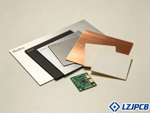
Every material family sits at a different point on the cost-versus-effort curve. Let me walk you through the main ones so you can plan your budget and lead time.
PTFE (Rogers RT/duroid, some RO3000):
- Best electricals. Dk near 2.1, Df as low as 0.0002–0.0004.
- Needs sodium-etch or plasma treatment before plating.
- Needs controlled drill parameters and CO₂ laser microvias.
- Highest cost. Fewer board houses can build it. I reserve it for satellite and high-end radar.
Hydrocarbon ceramic (Rogers RO4000):
- Near-PTFE electricals with near-FR4 processing.
- RO4350B and RO4835 carry UL 94V-0 and run on standard lines.
- Cost roughly 3–5× FR4. Wide use in wireless infrastructure.
Low-loss laminates (Panasonic Megtron, Isola):
- Megtron 6/7/8 use thermoset processing, so standard FR4 gear works.
- I have seen quote requests for Megtron rise fast. Customers like the performance.
- The catch is supply. Megtron carries longer lead times and higher cost because few shops stock it. The performance must justify that trade.
Mid-loss and advanced FR4:
- Isola FR408HR is proven to 6 GHz in production, including printed antennas. It is characterized to 10 GHz.
- Low-loss FR4 grades cost more than standard FR4 but far less than Rogers or Megtron. They power high-volume digital boards like PCIe 5.0.
At LZJPCB, Rogers is our most common specialty material. Isola comes next, and I personally favor Isola for research and documentation. A smart move for many designs is a hybrid stackup. You put Rogers on the signal layers and FR4 on the power and ground layers. You pay for low loss only where you need it.
How to Match an RF Material to Your Operating Frequency
Frequency is your first filter, but it is not your only one. Match wrong and you either overpay or lose your signal.
Match an RF material to frequency by targeting Dk and Df first, then checking thermal, impedance, and fabrication needs. Use FR4 below 500 MHz. Use Rogers or similar above 500 MHz. Above 3 GHz, advanced laminates are often needed. Above 30 GHz, only ultra-low-loss materials work.
Frequency sets the starting point, but board size, trace length, power level, and impedance tolerance all shape the final call. Let me give you a clear frequency map you can follow.
Material Selection by Frequency Range
Use this range guide as your first pass. Then adjust for trace length, power, and your board house capability. The selection sequence is: pick Dk and Df by frequency, then CTE and Tg by thermal environment, then thermal conductivity by power, then thickness by impedance, then check fabrication fit.
- Below 500 MHz: Standard FR4 works fine. Its limits do not bite here. Save your money.
- 1–5 GHz digital, short reach: FR4 or low-loss FR4 works if traces stay short. A 1–2 dB loss difference may not matter to your link budget. Pick the rational choice, not the fanciest.
- Sub-6 GHz RF (5G, Wi-Fi, IoT): RO4350B is my cost-optimized pick. Its Df of 0.0037 is enough here. FR408HR handles PCB antennas to 6 GHz.
- 6–20 GHz: RO4000 series hydrocarbon ceramic covers this range well. Megtron and Isola low-loss grades also fit.
- Above 20 GHz to mmWave: Move to PTFE. RO3003 and RT/duroid 5880 hold up here.
- 77/79 GHz automotive radar: Needs very low Df and rock-stable Dk across -40°C to +125°C. RO3003 is a common pick.
- Above 30 GHz analog: Loss scales with frequency. Df=0.005 at 30 GHz gives 6× the loss it gives at 5 GHz. Only the lowest-loss materials survive.
Remember one thing. Loss dominates over Dk value. A material with Dk=3.0 and Df=0.001 often beats Dk=2.2 and Df=0.003 for microwave work. You can tune impedance with trace geometry. You cannot tune away loss.
Common Mistakes in RF Material Selection
The wrong choice hides until the board is built. By then the fix is a full respin, not a quick edit.
The most common RF material mistake is choosing on datasheet Dk alone while ignoring Df stability, fabrication limits, and board house stock. Designers also skip prototyping, forget hybrid stackup stress, and pick a single supplier. Each of these turns into a delay or a failed build.
I have watched every one of these mistakes cost a project time and money. Here is my checklist to avoid them, drawn from over 300 projects I have run.
- Trusting single-point Dk: Dk shifts with frequency, temperature, and direction. Use the datasheet curves at your real operating frequency, not one number at 1 GHz.
- Skipping impedance testing: A datasheet is not enough. Run impedance coupon and TDR tests on the real board. Multiple lamination cycles can shift Dk from the spec value.
- Skipping prototypes: Build with the material before you commit to volume. Measure the real performance first.
- Ignoring copper roughness: At high frequency the copper surface adds loss through the skin effect. Pair low-loss material with VLP or HVLP copper foil.
- Forgetting hybrid stress: Mixing PTFE core with FR4 prepreg creates CTE mismatch. This can crack vias and cut yield. Match Dk across layers to avoid impedance jumps.
- Picking one supplier: A single source raises delay risk on every build. Approve two or more materials that meet the spec.
- Ignoring board house stock: Your shop may stock only a few RF materials. Non-stocked grades can add 2–4 weeks and an MOQ. Check availability before you specify.
- Forgetting thickness tolerance: Even with Dk under control, loose dielectric thickness swings your impedance. Confirm the thickness tolerance too.
My best advice is simple. Bring your fabricator in early. Our engineering staff help with stackup and material picks every day. We match your choice to what we can actually build and stock. This one step prevents most production delays.
FAQs About High Frequency PCB Materials
High frequency PCBs are boards that carry RF signals, usually above 1 GHz, where small material changes cause signal loss or distortion. Below are the specific answers engineers ask me about material choice, cost, and use.
What defines a high frequency PCB?
A high frequency PCB runs at frequencies above 1 GHz. At this point signal integrity becomes the main design concern. Small shifts in Dk, Df, or thermal coefficient can distort the signal or waste its energy.
Can FR4 ever work above 1 GHz?
Yes, in some cases. High-speed digital links like PCIe 5.0, which runs at 32 GT/s with a 16 GHz Nyquist, ship on low-loss FR4 in high volume. This works through short traces, careful routing, and receiver equalization. But for analog RF like amplifiers and filters, you should avoid FR4. There, loss directly cuts your signal-to-noise ratio and radiated power.
Why is PTFE so expensive to build?
PTFE needs special surface prep before plating, controlled drill settings, and often laser microvias. Its optical clarity can even resist laser ablation unless the wavelength is tuned. Fewer board houses can build it, which raises price further.
Is there one best RF material?
No. Every laminate trades off Dk stability, loss, CTE, Tg, cost, and buildability against each other. The best material is often the lowest-cost one that meets your link budget with margin and is available at your board house.
What is a hybrid stackup and when should I use it?
A hybrid stackup mixes materials, like Rogers signal layers over FR4 power and ground layers. Use it to cut cost when only some layers need low loss. Watch the CTE mismatch and match Dk across layers to avoid reflections.
Conclusion
Pick RF materials by Df and Dk stability, not brand. Match frequency, thermal needs, cost, and board house stock. When unsure, ask us early.