

Your radar board fails at 77GHz. The signal loss kills detection range. One wrong material choice ruins the whole ADAS module.
Car radar PCB manufacturing needs high-frequency laminates like Rogers or PTFE, tight impedance control, and IPC Class 3 assembly. These boards run at 24GHz and 77GHz, so material choice, via design, and SMT precision decide RF performance and long-term reliability.
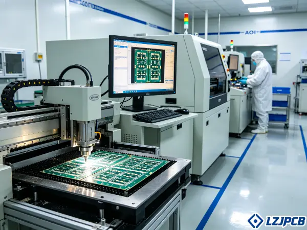
I have built radar boards for Automotive PCB clients for years. Small choices cause big problems at mmWave. Let me show you what really matters, step by step.
Car Radar PCB Materials: How to Choose Laminate for 77GHz and 24GHz
Pick the wrong laminate and your radar loses range. At 77GHz, even small loss adds up fast. The material is your first risk.
For 77GHz and 24GHz radar, choose low-Dk, low-Df high-frequency laminates such as Rogers or PTFE-based materials. These cut dielectric loss, hold a stable dielectric constant, and keep RF signals clean across temperature and frequency.
The wrong material wastes money and time. Here is how I pick the right one for each radar band.
Low-Dk and Low-Df Materials for High-Frequency Car Radar PCB
Dk is the dielectric constant. Df is the loss factor. Both matter a lot at radar frequencies. A low Dk keeps impedance stable. A low Df cuts signal loss.
At 77GHz, loss grows with frequency. So I always pick laminates with a Df below 0.002. This keeps the radar signal strong over distance.
A stable Dk also matters. If Dk shifts with temperature, the impedance shifts too. That breaks the radar timing.
Here is what I check for radar materials:
- Dk value: low and stable, around 3.0 to 3.5
- Df value: below 0.002 at 10GHz
- Dk shift over temperature: as small as possible
- Thickness control: tight and repeatable
I tell every client the same thing. The data sheet number is not enough. You must test the material at your real frequency. I have seen good-looking sheets fail in real radar tests.
PTFE-Based vs Hydrocarbon Laminates for Car Radar PCB
PTFE and hydrocarbon laminates both work for radar. But they behave differently. The choice depends on cost, process, and reliability.
| Feature | PTFE-Based | Hydrocarbon |
|---|---|---|
| Df at 10GHz | Very low | Low |
| Cost | Higher | Lower |
| Processing | Harder | Easier |
| Dimensional stability | Lower | Higher |
| Best use | 77GHz high range | 24GHz, mixed designs |
PTFE gives the lowest loss, so it fits long-range 77GHz radar. But PTFE is soft, it moves during drilling and lamination. My team uses special process control for it.
Hydrocarbon laminates are easier to build. They hold shape better and cost less. For many 24GHz designs, they work well.
I often mix materials in one stackup. We use PTFE for the RF layer and FR4 for power and control. This is a hybrid build. It saves cost and keeps RF clean.
Copper Foil Roughness Impact on Insertion Loss in Car Radar PCB
Copper roughness sounds small. At 77GHz, it is not. Rough copper adds insertion loss. The signal travels along the copper surface, so a rough surface fights the signal.
This effect is called the skin effect. At high frequency, current flows near the surface. Rough copper makes the path longer, more loss follows.
So for radar boards, I choose smooth copper. Here is my rule:
- Standard copper: too rough for 77GHz
- VLP copper (very low profile): good for radar
- HVLP copper (hyper very low profile): best for long-range radar
Smooth copper costs more. But it pays back in radar range. I always tell clients like Michael that copper choice is not a place to cut costs. One bad copper foil can drop the signal by a measurable amount. At radar level, that loss matters.
Car Radar PCB Manufacturing for Consistent RF Performance
You found the right material. Now the factory must build it right. Small process errors break the RF performance. Consistency is everything here.
Consistent radar RF performance comes from tight dielectric thickness control, clean via formation with backdrill, and low-loss solder mask. These steps keep impedance stable across every board, so your radar performs the same in volume production.
Building radar boards is not like building normal boards. Let me share the process points that decide your yield.
Dielectric Thickness Tolerances in Car Radar PCB Production
Dielectric thickness sets your impedance. If thickness changes, impedance changes. The radar then sees a different signal path. So we hold tight to thickness control.
For radar, I keep impedance control at ±5%. This needs careful press control during lamination. The prepreg flow must stay even.
Here is what we control in production:
- Lamination pressure and temperature
- Prepreg resin flow
- Layer alignment before pressing
- Thickness check after pressing
We measure every batch. We do not trust one sample. My team uses TDR to confirm impedance after build. This catches drift early.
For Michael’s industrial radar work, repeatability matters most. One good board is easy. A thousand good boards is the real test. That is why our Ji’an base runs ±5% impedance control as a standard, not as a special request.
Via Formation and Backdrill for Car Radar PCB
Vias carry the signal between layers. At radar frequency, a bad via adds loss and reflection. So via design needs care.
Via-in-pad is common in radar boards. It saves space and shortens the path. But the via must be filled and flat. A poor fit breaks the assembly later.
Backdrilling removes the unused via stub. The stub acts like an antenna. It causes reflection at high frequency. We drill it away.
Here is our via process for radar:
- Laser vias for HDI radar layers, down to small sizes
- Via-in-pad with resin fill and copper cap
- Backdrill to remove stubs on signal vias
- Clean drilling to avoid resin smear
We can build HDI structures like 1+N+1 and 2+N+2. These fit compact radar modules well. The any-layer interconnect helps route the dense RF and signal areas.
Solder Mask Selection for Low Attenuation on Car Radar PCB
Solder mask seems minor. On radar boards, it changes loss. The mask sits over the signal traces. Its material adds some attenuation. So we choose it with care.
Some radar designs leave the RF traces open with no mask. This cuts loss the most. But it needs other protection later, like conformal coating.
When mask is needed, we pick a low-loss type. The mask Df should stay low at high frequency. A thick mask adds more loss, so we keep it thin and even.
My approach for radar mask:
- Open the critical RF trace zones when possible
- Use low-Df mask over needed areas
- Keep mask thickness even and controlled
- Match mask choice with the surface finish
I pair the mask with the ENIG finish often. ENIG gives a flat surface and good corrosion resistance. For radar, flatness helps fine-pitch assembly. The two choices work together to protect RF performance.
Car Radar PCB Assembly: 5 Steps for Radar Module Integration
The board is built. Now the parts go on. Bad placement kills the radar signal. Assembly is where many radar projects fail.
Radar module assembly follows five steps: precise SMT placement, wire bonding for radar chips, reflow with tight control, AOI and X-ray inspection, then conformal coating. Each step protects RF signal integrity and module reliability.
The assembly for radar needs higher precision than normal boards. Here is how we handle the hard parts.
SMT Requirements for 77GHz Car Radar PCB Assembly
SMT placement accuracy decides RF performance. A part placed incorrectly shifts the signal path. At 77GHz, even a tiny shift matters. So we use high-precision machines.
Our placement accuracy reaches ±0.03mm for ICs. We handle 01005 parts and fine-pitch BGA down to 0.35mm. Radar chips often need this level.
Solder paste control matters too. We use 3D SPI to check paste before placement. Too much or too little paste breaks the RF joint.
Our radar SMT flow:
- Print paste with automatic printer and 3D SPI check
- Place parts with high-speed, high-accuracy machines
- Reflow with controlled multi-zone ovens
- Inspect with inline AOI
I always say placement is not just about putting a part down. For radar, the part must sit in the exact right spot. Our process keeps that accuracy across the full panel.
Wire Bonding Compatibility for Radar Chip Attachment
Some radar chips use wire bonding, not solder. The chip die connects to the board with thin wires. This needs a flat, clean pad surface.
ENIG finish helps here. It gives a flat gold surface for bonding. The bond wire sticks well to gold. Corrosion stays low over time.
Pad design matters for bonding. The pads must be clean and flat. Any roughness hurts the bond. So we control plating closely.
Key points for bonding-ready radar boards:
- Flat ENIG or ENEPIG surface finish
- Clean pads with no residue
- Tight pad size control
- Good board flatness during the bond step
I work with clients to match the board finishes to their bonding process. The wrong finish causes weak bonds. A weak bond fails under vibration in the car. So we plan this early in design.
Conformal Coating for Car Radar PCB Environmental Protection
A car radar lives in a hard place. Heat, water, salt, and vibration all attack it. Conformal coating protects the board. It seals the surface from moisture and dirt.
But coating must avoid the RF zones if they affect the signal. A thick coat over an antenna changes performance. So we mask those areas first.
The coating also helps with corrosion. This is key for automotive life. The radar must work for years in the field.
Our coating steps:
- Mask the RF and connector areas
- Apply even coating thickness
- Cure under controlled conditions
- Inspect coverage and edges
For radar, I match the coating type to the climate the car will face. A radar sold worldwide sees many conditions. The coating must protect it in all of them. This supports the AEC and IPC Class 3 reliability targets.
Car Radar PCB Testing Standards for Production Release
A radar board can look perfect and still fail. You cannot see RF loss. You must test it. Skipping tests means shipping bad boards.
Radar PCB production release needs insertion and return loss tests, TDR impedance checks, plus thermal cycling and humidity tests. These prove RF performance and automotive durability before any board leaves the factory.
Testing is the gate before shipping. Here are the tests I trust for radar boards.
Insertion Loss and Return Loss Tests for Car Radar PCB
Insertion loss tells how much signal the board loses. Return loss tells how much signal bounces back. Both matter for radar. Low loss and high return loss mean a clean signal.
We test these on coupons or real boards. We use the right frequency, up to the radar band. A board can pass at low frequency and fail at 77GHz. So we test at the true frequency.
What we measure:
- Insertion loss across the radar band
- Return loss at key frequency points
- Loss compared to the design target
- Batch-to-batch consistency
I push clients to set clear loss limits in the spec. Without a limit, we cannot judge pass or fail. A clear number lets us reject bad boards before they ship. This protects the radar range in the field.
TDR Verification for Car Radar PCB Impedance Control
TDR means Time Domain Reflectometry. It checks impedance along the trace. The radar needs stable impedance. TDR shows where the impedance drifts.
We run TDR on test coupons from each panel. The coupon matches the real stackup. So the result reflects the real board.
TDR catches problems like:
- Thickness drift in the dielectric
- Trace width error from etching
- Via mismatch points
- Impedance steps along the path
We hold impedance at ±5% for radar. TDR confirms this on every batch. If a panel drifts, we stop and check. I trust TDR more than a single design value. The real board can differ from the plan, and TDR shows the truth.
Environmental Tests: Thermal Cycling and Humidity for Car Radar PCB
A car radar faces hot summers and cold winters. It faces rain and humidity. The board must survive all of it. So we run environmental tests.
Thermal cycling moves the board between hot and cold many times. This stresses the solder joints and vias. Weak joints crack. The test finds them before the car does.
Humidity tests check moisture resistance. Water can cause corrosion and shorts. The test confirms the coating and finish hold up.
Our environmental test set:
- Thermal cycling across a wide range
- Humidity exposure over long hours
- Vibration tests for in-car shaking
- Combined stress checks for real conditions
These tests match AEC-Q200 and IPC Class 3 needs. For Michael’s global B2B sales, this matters a lot. His radar units ship worldwide. They must work in every market. Our tests prove they will.
Car Radar PCB Cost Drivers: From Material to Assembly
Radar boards cost more than normal boards. You want to know why. And you want to know where to save. Hidden costs surprise many buyers.
Radar PCB cost comes from three main drivers: the high-frequency material premium, the panel utilization and scrap rate, and the assembly complexity with its yield. Material and yield usually drive the biggest share of the price.
Let me break down the cost so you can plan your budget right.
High-Frequency Material Cost Premium for Car Radar PCB
High-frequency laminates cost far more than FR4. Rogers and PTFE materials carry a premium. This is the first big cost driver for radar.
The price comes from the special resin and the smooth copper. These give low loss but cost more to make. There is no cheap shortcut for true mmWave performance.
Ways to manage material cost:
- Use a hybrid stackup, RF material only where needed
- Pick hydrocarbon over PTFE when the band allows
- Right-size the board to use less material
- Plan the stackup early to avoid waste
I help clients balance cost and performance. You do not need the most expensive material everywhere. You need it where the RF signal lives. The rest can use cheaper FR4. This hybrid plan cuts cost without hurting the radar.
Panel Utilization and Scrap Rate Impact on Car Radar PCB Pricing
Boards are built on big panels. How many boards fit on a panel changes the price. Good panel use lowers cost per board. Poor use wastes material.
High-frequency material is costly. So waste hurts more here. A low scrap rate keeps the price down.
What affects panel cost:
- Board size and shape fit on the panel
- Spacing needed between boards
- Scrap rate from process defects
- Yield loss from RF test failures
We plan panel layout to fit the most boards safely. We also keep our defect rate low. Our PCB base runs a 99%+ on-time delivery rate with strong yield control. For radar, a low scrap rate is not just about speed. It is about saving costly material. That saving reaches your final price.
Assembly Complexity and Yield in Car Radar PCB Production Costs
Assembly adds cost too. Radar boards have fine-pitch parts, BGA, and wire bonding. These need precise work. Precise work takes time and skill.
Yield matters here as well. If many boards fail RF test after assembly, the cost per good board rises. So we aim for high first-pass yield.
Cost factors in assembly:
- Fine-pitch and small part placement
- BGA and X-ray inspection needs
- Wire bonding setup
- RF test time per board
Our SMT factories place 8 million parts per day with high accuracy. High volume and tight control keep the cost per board reasonable. A turnkey flow also helps. We handle board, parts, assembly, and test together. This cuts the handoff cost and lowers the total price for you.
Car Radar PCB Procurement: 4 Mistakes That Degrade Performance
You spec a radar board and it underperforms. The cause is often a buying mistake. These mistakes are easy to make and costly to fix.
Four common radar PCB procurement mistakes degrade performance: choosing wrong dielectric properties, ignoring registration accuracy, skipping assembly cleanliness standards, and overlooking RF test data. Each one hurts signal integrity and field reliability.
I have seen these mistakes many times. Let me help you avoid them.
Incorrect Dielectric Properties for Car Radar PCB Materials
The biggest mistake is the wrong dielectric. Buyers sometimes pick a material by name, not by data. But the Dk and Df at the radar frequency are what matter.
A material may have a great Dk at 1GHz. At 77GHz it can be different. So you must check the value at your real frequency.
How to avoid this mistake:
- Ask for Dk and Df at the radar frequency, not just low frequency
- Confirm the Dk stays stable over temperature
- Request the material data sheet and test report
- Match the material to your real band, 24GHz or 77GHz
I always review the material choice with the client at the start. A wrong dielectric is hard to fix later. It often means a full redesign. Catching it early saves a lot of money and time.
Registration Accuracy Oversights in Car Radar PCB Manufacturing
Registration means how well the layers line up. In radar boards, layers must align tightly. A small misalignment shifts the RF features. That changes performance.
Many buyers forget to ask about registration. They focus on trace width but skip layer alignment. Both matter for radar.
Points to check:
- Layer-to-layer registration spec
- Drill-to-pad alignment
- HDI via alignment for stacked structures
- The factory’s real registration capability
We control registration closely in our HDI and multilayer radar builds. Good alignment keeps the RF path right. I tell buyers to ask the factory for its registration data. A factory that cannot answer is a warning sign for radar work.
Assembly Cleanliness Standards for Car Radar PCB
Dirty boards fail in the field. Flux residue and dirt cause corrosion and shorts. At radar frequency, residue can even change the signal. So cleanliness is a real performance issue.
Many buyers skip cleanliness in the spec. Then the board passes early but fails after months in the car. This hurts your brand and your warranty.
Cleanliness steps we follow:
- Clean flux residue fully after reflow
- Run ionic contamination tests
- Keep an ESD-safe and clean assembly area
- Inspect for residue before coating
For automotive radar, cleanliness ties to IPC Class 3. The board must last for years. I push clients to set a clear cleanliness standard. A clean board is a reliable board. Skipping this step is one of the easiest ways to lose radar performance over time.
Conclusion
Car radar PCBs need low-loss materials, tight impedance control, precise assembly, and full RF and reliability testing. Pick a turnkey partner who proves all of it.