Skip to content
Your SMT line runs, but it feels slow. Manual steps stack up. Yield drops. Every hour lost costs money you cannot get back.
To automate SMT assembly for higher efficiency, add closed-loop equipment at each stage: automatic printers, inline SPI, smart feeders, vision-guided placement, closed-loop reflow profiling, inline AOI, and an MES that links them all. This cuts labor, defects, and changeover time while lifting First Pass Yield.
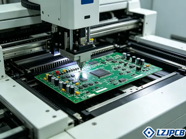
I have run more than 300 PCB and PCBA projects across 20 countries. I have seen where lines waste time and where automation truly pays back. Let me walk you through it step by step.
Where SMT Lines Lose the Most Time
Your line stops more than it runs. Operators wait. Boards queue. The problem hides in the small gaps that nobody measures.
SMT lines lose the most time at manual printing, manual inspection, feeder changeovers, and rework loops. These steps break the flow and force stops. Each stop drops throughput and hurts yield.
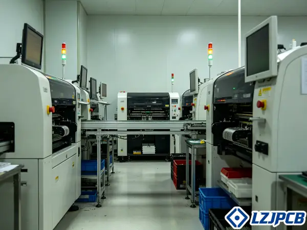
I always tell clients to find the stops first. You cannot fix what you do not see. Two areas cause most of the damage.
Manual Printing and Inspection Bottlenecks
Manual solder paste printing slows the whole line. An operator aligns the stencil by hand. The operator adjusts pressure by feel. This takes time and it varies from board to board.
Solder paste printing is the most used method to apply paste. The PCB stops under the stencil. A squeegee forces paste through the openings onto the pads. This step needs precise alignment and pressure control. When a person controls it, quality shifts.
Manual inspection makes it worse. Some printers offer an optional inspection system, but this is slow for large PCBs. Controlling the printing process matters because any print defect, if missed, causes defects further down the line. When you check by hand, you miss more. The line waits while you look.
Here is the chain of loss:
- Operator sets stencil position by hand, adding minutes per board
- Squeegee pressure varies, so paste volume changes
- Manual visual checks slow the flow and miss small faults
- Missed print defects travel to placement and reflow, causing rework later
The fix starts here. Fix the print, and you fix half your defects.
Slow Feeder Changeovers and Rework Loops
Feeder changeovers eat your day. Operators reload feeders by hand between jobs. On a high-mix line, this happens often. Each change stops placement.
Feeders sit on the placement machines. They deliver SMDs to the robot arms. The nozzles pick components and place them at set coordinates. When you swap feeders slowly, the machine idles. That idle time is pure loss.
Rework loops add a second drain. When a defect escapes, the board comes back. You find it, mark it, and repair it by hand. Non-good boards must leave the good flow and go for repair. This stops defects from spreading, but it also ties up labor and time.
Small-batch and high-mix work suffers most. If your business runs many jobs in small volumes, flexibility matters more than raw speed. Slow changeovers erase any speed gain your machines offer. I have watched lines with fast placement machines still lose to changeover delays.
Before You Automate: Audit Your Line
Do not buy machines yet. You risk spending on the wrong stage. Guessing wastes cash and leaves the real bottleneck untouched.
Before you automate, audit your line by measuring current throughput and OEE, then confirm your volume justifies the spend. Data shows you where to invest. It stops you from automating a stage that is not the true limit.
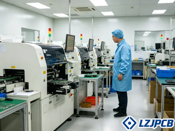
I run this audit with every client before I quote automation. Numbers beat opinions. Here is how I do it.
Calculate Your Current Throughput and OEE
Throughput tells you how many boards you finish per hour. OEE tells you how well your line uses its time. You need both before you spend.
OEE combines three factors: availability, performance, and quality. Availability is uptime versus planned time. Performance is real speed versus rated speed. Quality is good boards versus total boards. Multiply them, and you get OEE.
Here is a simple table to guide the math:
| Metric | What It Measures | How to Get It |
|---|---|---|
| Availability | Line uptime | Run time ÷ planned time |
| Performance | Real vs rated speed | Actual output ÷ rated output |
| Quality | Good board rate | Good boards ÷ total boards |
| OEE | Overall effectiveness | Availability × Performance × Quality |
Track First Pass Yield too. FPY improves when you automate more steps and cut rework. A low FPY points straight to a stage that needs help. When I audit a line, I look for the stage with the worst quality and the longest wait. That stage gets automation first.
Measure for at least a week. One day hides the pattern. A full week shows your real losses.
The Minimum Volume That Justifies Automation
Automation costs money up front. You need enough volume to earn it back. Below a certain volume, manual or semi-auto work makes more sense.
Your build type sets the rule. If you focus on large build quantities, placement rate leads. High volume spreads the machine cost across many boards, so payback comes fast. If you focus on small-batch and high-mix, flexibility leads. Here, smart feeders and quick changeover matter more than raw speed.
Use this guide:
- High volume, low mix: automate placement and reflow first for speed
- Low volume, high mix: automate feeder setup and inspection for flexibility
- Very low volume prototypes: keep flexible tools; full automation may not pay back
- Growing volume: automate the stage that limits you now, then scale
At LZJPCB, our SMT lines place 8 million components per day. That volume justifies full automation. Your line may not need that scale yet. Match the spend to the volume. Do not over-buy.
Printing and SPI Automation
Print defects cause most solder faults. A bad print ruins the board before placement even starts. You catch it late, and you pay in rework.
Automate printing and SPI with closed-loop printers and inline SPI. Closed-loop printers correct alignment automatically. Inline SPI measures paste volume per pad and flags faults before placement. Together they stop defects at the source.
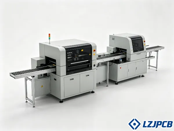
This is where I tell clients to start. Fix the print, and everything downstream gets easier. Here is how each piece works.
Closed-Loop Printers That Reduce Solder Defects
A closed-loop printer talks to the SPI machine. The SPI reads the print. If alignment drifts, the printer corrects itself. No operator needed.
SPI-to-printer networking allows automatic alignment adjustments between the PCB and stencil based on inspection data. The system sees the drift and fixes it before the next board. This keeps paste on the pads where it belongs.
Stencil design matters here too. For complex assemblies, the stencil design is a key success factor for repeatable and stable printing. As assemblies get more complex, stencil design gets more critical. A good stencil plus a closed-loop printer gives you a stable process run after run.
Jet printing is another path. It is becoming more popular in the sub-contract sector because it drops the need for stencils and makes changes easier. It is not yet the dominant method, but it helps high-mix lines that switch jobs often.
The result is fewer solder defects. Since print faults cause faults downstream, cutting print faults cuts total defects. That lifts your FPY and cuts rework labor.
Inline SPI That Flags Problems Before Placement
Inline SPI sits after the printer and before placement. It checks every board. It uses 3D technology to measure solder paste volume per pad, not just print area.
SPI captures images and compares four things against reference standards: paste position, surface quality, shape, and thickness or volume. It does this before any components are placed. This makes SPI a gating checkpoint. Nothing passes with bad paste.
When SPI finds non-conforming paste, engineers must pause the line and fix the problem before production resumes. This stops bad boards from moving forward. You lose a moment now to save many boards later.
Here is why 3D SPI beats in-printer checks:
- In-printer inspection uses 2D and measures print area only
- Dedicated 3D SPI measures paste volume per pad
- 3D data catches too-much and too-little paste, not just position
- A separate SPI machine avoids slowing the printer on large boards
I always recommend a dedicated SPI machine for volume work. It runs faster and catches more. That trade pays off in yield.
Placement and Reflow Automation
Placement and reflow decide your final quality. A drifted part or a bad heat profile ruins the board. These stages need tight control.
Automate placement and reflow with smart feeders, vision alignment, and closed-loop profiling. Smart feeders cut changeover time. Vision alignment stops placement drift. Closed-loop profiling keeps reflow yields stable. Each protects a different failure point.
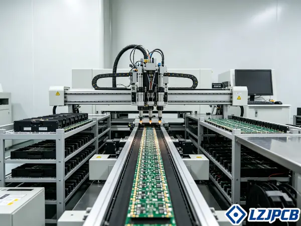
These three stages carry the most risk. I have seen good lines fail here. Let me break down each one.
Smart Feeder Setup That Slashes Changeover Time
Smart feeders speed up job changes. They track which reel sits in which slot. They verify the part before it runs. This kills the slow, error-prone manual setup.
A standard automatic line uses at least two mounting machines. One high-speed machine places small parts like resistors, ceramic capacitors, and inductors. One functional machine places larger parts like electrolytic capacitors, ICs, and connectors. Feeders on both must load fast and correctly.
Component packaging drives feeder needs. Reels are the preferred format. Tubes and trays work but need different feeders. Loose parts in bags should be avoided because they force hand placement or special feeding plates. Minimizing hand placement is a priority since it is slower and less repeatable.
Follow this feeder checklist:
- Order components on reels whenever possible
- Convert trays to tape-and-reel through a specialist service when needed
- Match feeder type to package format before the job starts
- Use verification to confirm the right part sits in the right slot
Smart feeder setup can slash changeover time from an hour to minutes. On a high-mix line, that gain is huge.
Vision Alignment That Prevents Placement Drift
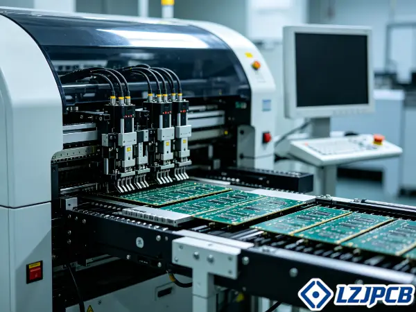
Vision alignment keeps parts on their pads. The machine picks each component with a vacuum or gripper nozzle. A vision system checks it. Then the machine places it at high speed in the programmed spot.
The vision check catches drift before it happens. It sees the part angle and position. It corrects the placement in real time. This gives accurate, repeatable placement even at high speed.
Support matters too. To place parts accurately and repeatably, you must fully support the PCB during placement. A board that flexes shifts your parts. Dedicated PCB support systems hold it flat.
Closed-loop feedback adds another layer. AOI-to-placement machine networking allows automatic adjustment of placement positions based on post-reflow results. If a part drifts on finished boards, the placement machine corrects itself. No operator steps in.
At LZJPCB, our machines hit ±0.04mm for chip components and ±0.03mm for ICs. We place down to 01005 parts and 0.35mm pitch BGAs. That precision comes from vision alignment plus proper board support.
Closed-Loop Profiling That Stabilizes Reflow Yields
Reflow soldering forms every electrical connection. It heats the board to melt the solder. The correct reflow profile is the key to good joints without heat damage. Get it wrong, and you lose the board.
The reflow process runs in phases: preheating, soak, reflow with the peak temperature where intermetallic compounds form, then controlled cooling. Ovens have 8 to 12 temperature zones. They come as standard air or nitrogen atmosphere types to match your paste and parts.
Lead-free soldering makes profiling harder. The required reflow temperature often sits very close to many components’ maximum rated temperature. This makes precise profiling more critical than with lead-based solder. Too little heat leaves weak joints. Too much heat kills the part.
Closed-loop profiling solves this. The system reads oven data and holds the profile steady across the whole run. It stabilizes yields batch after batch. Correct profiling prevents both weak joints and component damage.
I always match the oven type to the job. Nitrogen ovens help sensitive parts and fine pitches. Air ovens work for standard builds. The profile, not just the oven, decides the outcome.
Inspection Automation
Manual inspection is slow and misses faults. A tired operator overlooks a bridge. Bad boards slip through and reach the customer.
Automate inspection with inline AOI that scans every board. Inline AOI cuts manual checking labor and catches defects a person misses. It separates bad boards from good ones so defects stop spreading.
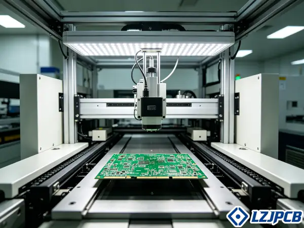
Inspection is your safety net. When you automate it, you protect both yield and reputation. Here is how inline AOI changes the game.
Inline AOI That Cuts Manual Checking Labor
Inline AOI scans boards automatically. It uses optical cameras and computer analysis. Newer machines use three-dimensional scanning for more complete defect detection than 2D systems.
AOI works at two points. Pre-reflow AOI checks component presence, type, value, and polarity before the oven. This catches placement errors before soldering locks them in. Post-reflow AOI checks solder joint quality after the oven.
3D AOI beats 2D for a clear reason. 2D systems produced high levels of false calls due to image interpretation limits. 3D AOI takes more accurate measurements, reduces false calls, and gives a more stable inspection process. Fewer false calls mean less wasted operator time.
When inline AOI finds a bad board, it separates it right away. The bad board goes for repair, the good boards move on. This stops defective units from progressing further.
Add X-ray for hidden joints. For boards with BGAs, X-ray inspection is non-destructive and checks the solder balls under the component after reflow. It finds breaks, pinholes, voiding, and solder hole fill. AOI and X-ray together cover what the eye cannot see.
At LZJPCB, we run 3D SPI, inline AOI, and X-ray on our lines. This dual inspection cuts labor and lifts yield at the same time.
Connecting Everything With an MES
Islands of automation do not add up. Each machine works alone, data stays trapped. You cannot see the line as one system.
Connect everything with an MES so machines share data in real time. An MES links SPI, placement, reflow, and AOI. Real-time data stops defects from spreading and enables closed-loop control across the whole line.
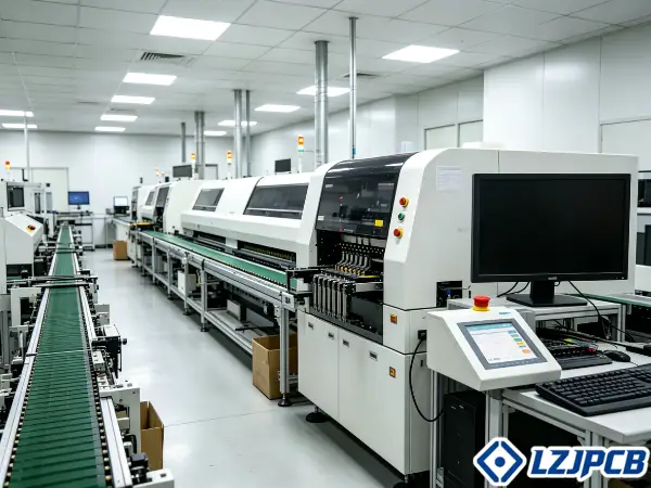
This is the step that turns separate machines into one smart line. Without it, you lose the biggest gains. Let me show you why.
Real-Time Data That Stops Defects From Spreading
An MES collects data from every machine as it runs. It sees the print, the placement, the reflow, and the inspection results. It links them into one live picture.
Networking is one of the newest features, so not every line has it yet. That gives early adopters an edge. Networked inspection machines enable closed-loop control in two key spots. SPI-to-printer feedback adjusts stencil alignment automatically. AOI-to-placement feedback corrects placement positions automatically.
Real-time data stops defects from spreading in a direct way. When SPI flags bad paste, the line pauses and the printer corrects. When AOI finds drift, the placement machine adjusts. The problem gets fixed before more boards go bad.
Here is what an MES delivers:
- Live view of every stage in one place
- Automatic correction between linked machines
- Full traceability from bare board to finished PCBA
- Fast root-cause analysis when a defect appears
For Michael and buyers like him, traceability matters most. A German industrial buyer needs to track production progress and quality control. An MES gives that visibility. You see the status of every batch, every day. That solves a real pain point in cross-border sourcing.
Automation Mistakes That Backfire
Automation can go wrong. You buy fast machines and see no gain. The problem moves instead of disappearing.
The two mistakes that backfire most are poor feeder management and skipped line balancing. Poor feeder management erases your speed gains. Skipped line balancing creates new bottlenecks. Both waste your investment.
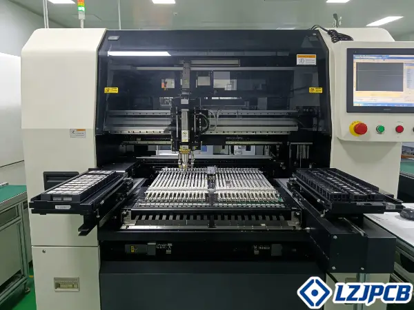
I have fixed lines that spent big and gained little. The cause was almost always one of these two. Here is what to watch.
Poor Feeder Management That Erases Speed Gains
Poor feeder management kills your fast placement machines. The machine can place at high speed, but it sits idle waiting for feeders. Slow changeovers erase the gain.
Wrong packaging causes much of this. Loose parts in bags force hand placement or special feeding plates. Tubes and short tape strips, often used because of MOQs, need different feeders than reels. When you mix formats without a plan, setup slows down.
MSL parts add another trap. Components with a Moisture Sensitivity Level must be handled per J-STD-033 before use. Skip this, and the part fails in reflow. That is a defect you created, not caught.
Manage feeders with these steps:
- Standardize on reels; convert trays to tape when possible
- Plan feeder slots before the job, not during it
- Handle MSL parts per J-STD-033 to avoid reflow damage
- Verify each feeder loads the correct part before running
Good feeder management protects the speed you paid for. Skip it, and your fast machine runs slow.
Skipped Line Balancing That Creates New Bottlenecks
Line balancing spreads the work evenly across stages. Skip it, and one stage falls behind. That slow stage becomes your new bottleneck. The line runs no faster than its slowest step.
This happens when you automate one stage but not the flow. You buy a fast placement machine. Now the printer or the AOI cannot keep up. Boards pile up in front of the slow stage. Your throughput does not rise.
The complete SMT sequence has many steps: loading, paste printing, SPI, placement, pre-reflow AOI, reflow, post-reflow AOI, and more. Each takes time. If one step runs much slower than the rest, it drags everything down.
Balance the line with these checks:
- Measure cycle time at each stage, not just the machine you upgraded
- Match the speed of feeding stages to your placement rate
- Add SPI or AOI capacity if inspection becomes the limit
- Re-audit after each change, since fixing one stage can expose another
The goal is efficiency without losing quality. That is a dual imperative. Balance the line, and you get both. Skip it, and you trade one bottleneck for another.
ROI and Payback Period
Automation is an investment, not a cost. But you need the numbers. A guess on payback leads to a bad decision.
Calculate ROI and payback by dividing your equipment cost by the yearly savings from labor, rework, and faster delivery. Higher volume shortens payback. A clear FPY gain speeds it up further.
I help clients run this math before they buy. It turns a big spend into a clear decision. Here is the method.
How to Calculate the Payback on Your Equipment
Start with the total equipment cost. Include the machine, install, training, and any support systems. That is your investment.
Next, add up your yearly savings. Automation saves in three main areas. It cuts labor cost by removing manual steps. It cuts rework cost by lifting First Pass Yield through more automation. It cuts lead time, so you deliver faster and take more orders.
Use this simple frame:
| Savings Source | How It Saves | How to Estimate |
|---|---|---|
| Labor | Fewer manual steps | Hours saved × wage × workdays |
| Rework | Higher FPY | Rework cost per board × boards saved |
| Lead time | Faster delivery | New orders × margin |
| Scrap | Fewer escaped defects | Scrap cost × defect drop |
Then apply the payback formula. Divide the total equipment cost by the yearly savings. The result is your payback period in years.
Two things shorten payback. Higher volume spreads the machine cost across more boards. A larger FPY gain saves more rework per board. The cost of field failures, the defects that escape, usually exceeds the cost of testing. That is why inspection automation pays back well. It stops escaped defects before they reach your customer.
FAQ on SMT Automation
You still have questions. Buyers always do. Here are the ones I hear most from engineers and procurement teams.
What is the difference between SMT and through-hole?
SMT places and solders components directly onto pads on the board surface. Through-hole uses drilled holes for leads. SMT was developed mainly to cut manufacturing cost and use board space better. SMDs reduce size and weight by 60% to 90% compared to through-hole parts, which enables finer designs and smaller products.
Do I need both ICT and functional testing?
Yes, they are complementary, not a replacement for each other. ICT detects opens, shorts, and checks passive component values on the assembled board. It cannot verify how the finished product operates. Functional testing verifies the board works under real or simulated operating conditions. ICT runs first, then functional testing, as the final quality gate.
When does a board need conformal coating?
Conformal coating is not universal. Apply it when boards face environmental exposure, need high-voltage safety, or require extended working life. It is a thin polymeric film, usually 25 to 250µm thick, that protects solder joints, leads, traces, and metallized areas from corrosion.
Why is cleaning still needed with No-Clean flux?
Cleaning stays essential in some cases even with No-Clean flux. You need it when boards get conformal coating, when aesthetics matter, or when flux residues could cause current leakage paths in high-voltage applications.
Can I automate a small-batch, high-mix line?
Yes, but prioritize flexibility over raw speed. Smart feeders and fast changeover matter more than placement rate for high-mix work. Automate feeder setup and inspection first. Full high-speed automation may not pay back at very low prototype volumes.
What data do you need to program the machines?
CAD data is best for placement machines and AOI. Gerber data is almost always available since it is required for bare PCB manufacturing, and it works as an alternative. Using Gerber is less efficient because placement data must be extracted indirectly.
Conclusion
Automate SMT assembly stage by stage, link it with an MES, manage feeders, balance the line, and confirm payback. This lifts efficiency without losing quality.