 Skip to content
 You buy a PCB board for a patient monitor. It malfunctioned, causing a delay in diagnosis. In medical devices, a board failure is a patient risk.
A medical PCB is a printed circuit board built to Class 3 standards for use in medical devices. It demands higher reliability, full traceability, lead-free assembly, and certifications like ISO 13485. Patient safety drives every design and manufacturing choice.
I have managed over 300 PCB projects, many in medical. The gap between a standard board and a medical board is wider than most buyers think. Let me show you exactly where it matters.
How Does a Medical PCB Differ From Standard PCBs?
You assume a PCB is a PCB. Then a board in an infusion pump quits, and now a patient misses a dose. Medical is different.
A medical PCB differs from a standard PCB in reliability, traceability, and certification. It must be built to IPC Class 3, use lead-free assembly, and link every board to its component lot. A standard PCB has none of these demands.
Medical devices run inside a healthcare system. That system needs safety, consistency, and reliability at all times. This puts heavy pressure on us as manufacturers. I treat every medical board as if a patient depends on it, because one does.
Definition of a Medical PCB in Electronic Medical Devices
A medical PCB is a printed circuit board made for electronic medical devices. Today, almost every diagnostic, research, and treatment method runs on computers. So medical PCBs are now a standard need across the whole industry, not a niche part.
These boards power pacemakers, MRI scanners, CT scanners, diagnostic tools, sensors, wearables, infusion pumps, and ECG machines. Each device has its own job. The board must support that job with no failure. A medical PCB must be made to Class 3 electronic requirements. That is a higher bar than general consumer electronics. The board must work with safety, consistency, and reliability under real healthcare conditions. Patient safety is the reason behind every one of these rules.
5 Key Differences Between Medical PCB and Commercial PCB
I see five clear differences when I move a design from commercial to medical. Each one adds cost and time, but each one protects the patient.
| Difference | Commercial PCB | Medical PCB |
|---|---|---|
| Quality class | IPC Class 2 | IPC Class 3, 100% electrical test |
| Traceability | Not enforced | Each board linked to batch and lot numbers |
| Assembly | Lead allowed | Lead-free assembly, no exceptions |
| Reliability | Standard parts | Long-life, highly reliable parts as a baseline |
| Review cycle | Short | Class 3 design review adds about 1 month |
IPC Class 3 boards need 100% electrical testing, not sample testing. They also use tighter acceptance rules than Class 2. The traceability system links each board to its source batch and component lot. Consumer electronics rarely need this.
Why Standard PCB Cannot Meet Medical Device Requirements
A standard PCB cannot meet medical needs because the cost of failure is too high. When a commercial board fails, you lose a product. When a medical board fails, you risk a life.
A PCB failure in an implantable device is a direct, immediate health risk to the patient. A failure in a diagnostic machine delays diagnosis. That delay can stop a doctor from assessing a patient. For medical PCBs, device downtime means a break in patient care. That is not true for commercial or industrial boards. Medical devices also need very reliable and long-lasting parts as a baseline, not as an upgrade. A standard board is not built, tested, or documented to this level. So it simply cannot serve a medical role.
7 Types of Medical PCB for Different Device Applications
You picked the wrong board type. The device is too big to wear. Or it cracks when it bends. The type must match the device.
The main medical PCB types are HDI, flexible, rigid-flex, rigid, single-layer, double-layer, and multilayer boards. Each fits a specific device. HDI suits implants, flex suits wearables, multilayer suits imaging systems. The right type matches the device shape and function.
Medical devices often break the normal shape and size rules. They force non-standard form factors. So we use three construction types for three-dimensional shapes: rigid, flexible, and rigid-flex. The trend toward less invasive devices pushes us toward smaller, denser boards. I always start by asking where the board must fit and how it must move.
HDI Medical PCB for Compact Implantable Devices
HDI medical PCBs solve the size problem. They pack a high connection density into a very small board area. This directly answers the size limits of implantable and portable devices.
HDI PCB technology shrinks the board through laser-made via holes, not general tricks. These tiny vias free up space and add high-speed connectivity. That makes HDI ideal for sensors and wearables. We build HDI types 1+N+1, 2+N+2, and 3+N+3, with laser holes down to 4mil. For highly integrated parts like BGAs or chips with many pins, we use via-in-pad. This drills holes right onto the component pads to reach the inner layers. The demand for less invasive medical devices keeps pushing HDI use higher every year.
Flexible and Rigid Flex Medical PCB for Wearable Monitors
Flexible and rigid-flex PCBs solve two problems at once. They fit into small, odd spaces and still resist damage. This makes them the top choice for wearable monitors.
Flexible PCBs use materials that bend and fold. That lets a patient wear the device right on the body. Flex boards suit any spot that needs to bend, including designs that fold. In dynamic use, we rate flex board life at 100,000 to 1,000,000 bend cycles. Rigid-flex PCBs mix flexible inner layers with outer FR-4 rigid layers. We remove unwanted FR-4 with a laser to expose the flex sections. This gives the flexibility of flex circuits and the durability of rigid boards. A rigid-flex board is more durable than flex, yet lighter and smaller than rigid.
Rigid Medical PCB for Diagnostic Imaging Equipment
Rigid medical PCBs serve large, stable diagnostic machines. They hold many parts on a strong, flat base. This fits imaging gear that does not move or bend.
Medical imaging PCBs for CT scanners, MRI, and ultrasonic equipment must hold high-speed signal integrity. They also need controlled stack-ups. We design the layout to avoid crosstalk, ground bounce, and signal reflections. For high power density, we sometimes use ceramic PCBs. Ceramic substrates like Alumina or Aluminum Nitride have far higher thermal conductivity than FR-4. Ceramic boards work at very high temperatures, resist chemical erosion, and have a low thermal expansion rate. This makes them strong choices for surgical and imaging devices that run hot.
Single Layer vs Double Layer vs Multilayer Medical PCBs Compared
The layer count grows with device complexity. A simple sensor needs one layer. A CT scanner needs many. Here is how I match them.
| Type | Layers | Routing | Medical use |
|---|---|---|---|
| Single layer | One conductive layer | Limited | Simple sensors, temperature monitors, heart-rate sensors |
| Double layer | Two conductive layers | More options | Infusion pumps, ECG machines |
| Multilayer | Many alternating layers | High density | CT scanners, MRI machines |
Single-layer boards have one conductive layer on a substrate. Double-layer boards add a conductive layer on both sides. That gives more routing room. Multilayer boards stack alternating substrate and conductive layers. They give high routing density and hold many tiny parts in a small space. So they fit the most complex imaging machines.
Medical PCB Compliance Requirements You Must Meet
You ship a board without ISO 13485. The buyer rejects the whole lot. Compliance is not paperwork. It is your entry ticket.
Medical PCBs must meet ISO 13485, IEC 60601, FDA rules, IPC standards, and RoHS. These cover the quality system, electrical safety, design control, assembly reliability, and hazardous material limits. Missing one can block your product from the market.
Shawn, my typical buyer, always asks for certificates first. I understand why. A board can look perfect and still fail an audit. So I keep our records ready. We hold ISO9001, ISO14001, IATF16949, ISO13485, UL, CUL, RoHS, and REACH. Below I explain what each standard actually controls.
ISO 13485 Certification for Medical PCB Manufacturing
ISO 13485 is the core medical standard. It sets the Quality Management System rules for medical device organizations. Without it, most medical buyers will not even start a conversation.
ISO 13485:2016 spells out the QMS needs for any firm that makes medical devices or their parts. It sits on top of ISO 9001:2015, which covers quality during PCB design, manufacturing, and assembly. ISO 9001 handles general quality. ISO 13485 adds the medical layer, with strict focus on risk and traceability. We are ISO13485 certified, so we run our medical lines under this system. For a buyer, this certificate is proof that our process is built for medical work, not adapted from commercial work.
IEC 60601 Standard for Medical Electrical Equipment Safety
IEC 60601 covers safety. It deals with the safety and performance of medical electrical equipment. Your PCB assembly methods must meet the rules.
This standard from the International Electrotechnical Commission protects both patients and operators. It checks things like leakage current, insulation, and creepage distance. When I design a board for an IEC 60601 device, I plan the layout and clearances to pass these tests from the start. Fixing this late costs time and money. So I treat IEC 60601 as a design input, not a final check. This keeps the device safe to touch and safe to use near a patient.
FDA Regulations for Medical Device Printed Circuit Boards
The FDA controls medical devices sold in the United States. This includes any device with a PCB assembly inside. You cannot skip it for the US market.
The US Food and Drug Administration requires full documentation, design control, and validation. This means we must show how the board was designed, made, and tested. We must prove each step is controlled and repeatable. For a buyer selling into the US, this paper trail matters as much as the board itself. I help clients keep design records clean so they can move through FDA review without surprises. Good documentation now saves a failed submission later.
IPC Standards for Medical PCB Assembly and Reliability
IPC standards set the bare-board and assembly quality rules. They define what is acceptable and what is a defect. For medical, we apply the strictest class.
| IPC Standard | What It Controls |
|---|---|
| IPC-A-600 | Acceptable conditions for bare circuit boards |
| IPC-A-610 | Acceptability of electronic assemblies |
| IPC-6012 | Performance and qualification for rigid PCBs |
IPC Class 3 is not a best practice for medical. It is a requirement. It ensures safety, reliability, and a long lifecycle. Class 3 boards need 100% electrical testing, not sample testing. They also use tighter acceptance rules than Class 2. We run 100% electrical test plus dual AOI on every board. This is how we hit a 99%+ on-time and reliability record.
RoHS Compliance for Medical PCB Used in Europe
RoHS controls hazardous materials. It restricts certain harmful substances during PCB manufacturing and assembly. For Europe, this is a baseline rule you must meet.
The Restriction of Hazardous Substances directive limits things like lead and certain flame retardants. Medical PCBs must comply with RoHS as a basic material rule. Beyond RoHS, medical board materials must show five abilities: RoHS compliance, connectivity support like WiFi and Bluetooth, high-frequency signal transmission, high-speed signal transmission, and good heat resistance up to the max operating temperature. We supply RoHS and REACH reports with SVHC data. For Shawn in Germany, this is non-negotiable before any order ships.
Where Are Medical PCBs Used: 6 Common Medical Device Applications
You think medical PCBs sit only in big hospital machines. Then you check your own glucose monitor, they are everywhere now.
Medical PCBs are used in pacemakers, patient monitors, diagnostic imaging, surgical robots, infusion pumps, and home healthcare devices. They power cardiovascular implants, imaging systems, wearable monitors, and drug delivery tools. Almost every modern medical device relies on one.
Because the whole industry now runs on computers, medical PCBs show up across diagnosis, research, and treatment. I have built boards for many of these uses. Each one has its own reliability target. Below are six areas where these boards do the most important work.
Medical PCB in Pacemakers and Implantable Devices
Pacemakers and implants need the most reliable boards we make. A failure here is a direct, immediate health risk to the patient. There is no room for error.
Cardiovascular devices like pacemakers, defibrillators, and heart monitors form a distinct use case. They have their own reliability rules. These devices live inside the body, so the board must be tiny and last for years. We use HDI technology to pack high density into a small space. We also pick long-life parts and run full traceability. I review every implant board myself, because the stakes are simply too high to delegate.
Patient Monitoring Systems Using Medical PCB
Patient monitoring systems watch vital signs around the clock. They need boards with high reliability and a long lifespan. A glitch can hide a real problem.
Patient-worn and self-use monitors need PCB integration. This includes body temperature monitors and blood glucose monitors. Two specific sub-types stand out: blood glucose monitors and wireless blood pressure readers that link to a smartphone. Both need boards with proven reliability and long life. Hospital call and alarm systems also need these two traits. I design these boards to run for years without drift, so the readings stay accurate every single shift.
Diagnostic Imaging Equipment Powered by Medical PCB
Diagnostic imaging machines turn signals into images. They need boards with high-speed signal integrity. A weak board gives a blurry or false image.
Medical imaging systems like MRIs, CT scans, and ultrasonic equipment form a major application cluster. These imaging PCBs must keep high-speed signal integrity and use controlled stack-ups. I design the layout to block crosstalk, ground bounce, and signal reflections. For high power, I may use ceramic boards with high thermal conductivity. A failure in these machines delays diagnosis. That can stop a doctor from properly assessing a patient. So signal quality here is a clinical issue, not just an engineering one.
Medical PCB in Surgical Navigation and Robotic Systems
Surgical navigation and robotic systems guide the surgeon in real time. They need fast, stable, and safe boards. A delay during surgery is dangerous.
These systems mix high-speed signal transmission with flex or rigid-flex construction. That mix guarantees reliable performance in hard conditions. Surgical lighting in these setups needs two things: good heat management and a long lifespan. The board must run hot and still last. I mitigate EMI and EMC risk with four steps: careful stackup design, smart routing, filtering, and shielding. This keeps the navigation signal clean while the robot moves. Reliability under stress is the whole point.
Infusion Pumps and Drug Delivery Device PCB
Infusion pumps deliver drugs at set rates. The board controls the dose and timing. A board fault can mean a wrong dose to the patient.
Infusion pumps and ECG machines often use double-layer PCBs. The two conductive layers give enough routing for the control logic. These devices must run with no errors over long periods. I design them with test points on the signal traces, so technicians can check function fast. Drug delivery is precise work. The board has to hold that precision for the full life of the device. We use long-life parts and full electrical testing to back this up.
Home Healthcare Device Applications for Medical PCB
Home healthcare devices move care from the hospital to the home. They need small, friendly, and reliable boards. Patients use them without a technician nearby.
Miniaturization, driven by PCB integration, shrinks these devices and makes them easier to use. But smaller size brings design limits that need special engineering. We also see air respirators here. These rely on PCBs for both power delivery and air purification. Some home devices must work in extreme environments. The board must stay reliable in all of them, not just in normal conditions. I balance small size with strong reliability, because a home user cannot fix a fault themselves.
4 Major Challenges in Medical PCB Design and Manufacturing
You finalize a design. Then a key part goes obsolete. Now you may need a new license. Medicine brings hard, hidden challenges.
The four major challenges in medical PCB are high reliability demands, component sourcing limits, facility approval and validation costs, and method validation for each batch. Each adds time and cost. Together they make medical PCB far harder than standard production.
In my seven years of medical PCB work, these four challenges show up again and again. They are not edge cases. They shape the whole project plan. The Class 3 design review alone usually adds about one month to the schedule versus an industrial board. I tell clients this early so the timeline is honest.
High Reliability Requirements for Medical PCB in Critical Devices
Critical devices demand near-perfect reliability. Medical devices need very reliable and long-lasting parts as a baseline. This is the starting point, not a bonus.
The reason is simple. Device downtime means a break in patient care. So I design for the long term from day one. I use IPC Class 3, which gives 100% electrical testing and tighter acceptance rules than Class 2. I also optimize the layout to avoid crosstalk, ground bounce, and signal reflections. Following DFM and DFA guidelines is a must here, not an option. These rules raise assembly efficiency and cut defects. High reliability is built into the process, not tested at the end.
Component Sourcing Limitations for Medical Grade PCB
Component sourcing in medical is tight. Parts may need to be very small or densely packed. This creates reliability and fabrication challenges.
Part limits come from extreme size and density needs. Some materials cause trouble too. Copper and silver can be unsuitable for some uses because they react with other materials. So I must pick parts and materials with care. If a part is discontinued, I need an alternative solution. If that change is big, it can trigger a new regulatory approval and a new license. Our 20+ supply chain staff handle this. They source from original makers and tier-1 agents, with 100% genuine and traceable parts. This protects the design from sudden gaps.
Facility Approval and Validation Costs for Medical PCB Production
Facility approval adds real cost before any sale. We must keep equipment properly calibrated. We must run effective quality checks before any medical board can be sold.
This is not a one-time step. We maintain calibration logs and quality records all year. We run annual supplier audits and use a D-grade elimination system to drop weak suppliers. All of this costs money and time. But it is the price of selling into medical. A buyer like Shawn pays a fair premium for this. In return, he gets a board he can trust and document. I see this cost as an investment in patient safety and in our shared reputation.
Method Validation Requirements for Each Medical PCB Batch
Method validation runs on each batch, not just once. We verify the environmental conditions of the manufacturing space. We confirm proper parameters at every production step.
This means each medical batch carries proof that it was made under controlled conditions. We check temperature, humidity, and process settings at each stage. This is tied to our traceability system, which links each board to its batch and component lots. Consumer electronics rarely enforce this, but for medical, it is standard. I know it slows things down. But it is the only way to prove a batch is safe and consistent. When a buyer asks for batch records, we have them ready.
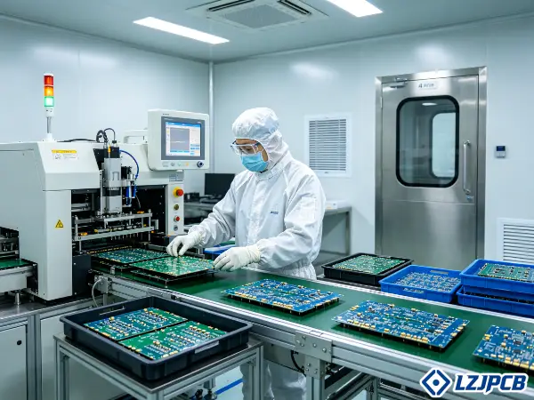
Medical PCB Assembly Process: What Makes It Different
You assume assembly is just soldering parts. Then you skip the clean room. Now contamination ruins the batch. Medical assembly has rules.
Medical PCB assembly differs through clean room control, full component traceability, and strict testing. It uses fully lead-free SMT, with X-ray for BGAs and nitrogen reflow when needed. Every board links to its batch, and 100% testing is the norm.
Lead-free assembly is mandatory for all medical PCB production, with no exceptions. Our SMT lines can place 8 million parts per day. But for medical, speed is not the point. Control is. Below, I walk through what makes our medical assembly different from a standard line.
Clean Room Requirements for Medical PCB Assembly
Medical assembly needs a controlled clean space. We run a Class 100K cleanroom for our FPC and sensitive work. This keeps dust and particles off the board.
Before installation, every medical PCB must be thoroughly cleaned to remove excess buildup. This is a prerequisite for full function on install, not a suggestion. A speck of debris can cause a short or a failed bond. We also control temperature and humidity in the space. Our method validation checks these environmental conditions for each batch. So the clean room is part of the validated process. I never let a medical board skip this step, because contamination is invisible until the device fails.
Traceability Requirements for Medical PCB Components
Traceability links every board to its source. Medical PCBs typically need a documented system linking each board to its manufacturing batch and component lot numbers. Consumer electronics usually skip this.
This system lets us trace a fault back to a specific lot. If a part later shows a problem, we know exactly which boards used it. We source parts from original makers and tier-1 agents, all genuine and traceable. We run IQC inspection on incoming parts. We store them with FIFO, temperature and humidity control, and ESD safety. So the trace chain starts at receiving and runs to the finished board. For a medical buyer, this record is proof and protection at the same time.
Testing and Debugging Protocols for Medical PCB
Medical boards get full testing, not sample testing. IPC Class 3 needs 100% electrical testing. We also run dual AOI on every board.
Our lead-free SMT process runs in a set order: solder paste printing, solder paste inspection, pick-and-place, reflow soldering, then AOI. For double-sided boards, the line runs the board twice. For boards with BGAs or hidden joints, we add X-ray inspection after reflow. If a board oxidizes easily, we shift to nitrogen reflow. For through-hole work, lead-free THT is half-automatic and only used when the board has plated through-holes.
The order is: insert leads through PTH holes, then wave soldering. If the board is heat-sensitive, we shift to selective soldering. We also place test points on signal traces for easy debugging.
How to Select a Qualified Medical PCB Manufacturer
You pick a cheap supplier. The boards pass at first. Then quality drifts. In medicine, the wrong factory is a real risk.
To select a qualified medical PCB manufacturer, verify ISO 13485 and IPC Class 3 capability, check industry experience, and confirm full traceability. Ask about testing, sourcing, and validation. Avoid suppliers without medical certificates or batch records. Choose proven medical expertise over the lowest price.
Shawn focuses on two things when sourcing: the factory must have experience in his industry, and it must hold the right certificates. I agree. A good medical partner gives more than a board. It gives dedicated engineers, full records and a clear process. We support custom development one-on-one, while many competitors only offer a website order form. Here is how to judge a supplier.
8 Questions to Ask About Medical PCB Manufacturing Capabilities
The right questions reveal a real medical factory fast. A weak supplier will dodge them, but a strong one will answer with proof.
| # | Question to Ask |
|---|---|
| 1 | Are you ISO 13485 certified for medical work? |
| 2 | Can you build to IPC Class 3 with 100% electrical testing? |
| 3 | Do you offer full batch and component lot traceability? |
| 4 | Do you run lead-free SMT and X-ray for BGAs? |
| 5 | Do you have a clean room for medical assembly? |
| 6 | What is your experience in my specific device field? |
| 7 | Do you provide dedicated engineers for custom work? |
| 8 | How do you handle obsolete components and re-validation? |
These eight cover quality, traceability, process, and support. We answer yes to all of them. We have 50+ design engineers and an EMS team with 10+ years of experience. I always tell buyers to ask for proof, not just a yes.
Certificates to Verify Before Ordering Medical PCB
Always verify certificates before you order. Paper claims are easy. Real, current certificates are not. Check them yourself.
| Certificate | What It Proves |
|---|---|
| ISO 13485 | Medical device quality system |
| ISO 9001 | General quality system |
| IEC 60601 readiness | Electrical safety capability |
| RoHS / REACH | Material and hazardous substance compliance |
| IATF 16949 | Strong process control (automotive-grade) |
| UL / CUL | Safety listing |
We hold all of these, plus 20+ patents and China National High-Tech Enterprise status. Ask for the certificate number and expiry date. A real factory shares them without delay. If a supplier stalls or gives vague answers, treat that as a warning sign.
Red Flags to Avoid When Sourcing Medical PCB
Some warning signs are clear once you know them. Spotting them early can save you from a failed batch or a market block.
The first red flag is no ISO 13485. No medical quality system means no real medical work. The second is no traceability. If they cannot link a board to its lot, you cannot defend a recall. The third is sample-only testing. Medical needs 100% testing, not spot checks. The fourth is a refusal to support obsolete parts. A discontinued part may need an alternative and even new approval, so the supplier must help. The fifth is only a website order form with no engineer contact. Medical work needs human support. I see these signs often, and they almost always lead to trouble later.
Frequently Asked Questions About Medical PCB
You still have questions before you buy. Lead time, MOQ, cost, certificates. Let me answer the ones I hear most.
Common medical PCB questions cover lead time, MOQ, cost, and certification. Lead time is longer due to the Class 3 review. Low MOQ prototyping is possible. Medical PCBs cost more than standard. Most, but not all, medical PCBs require ISO 13485.
These four questions come up in almost every medical quote I send. I want to answer them plainly here, so you can plan your project with no surprises. Honest answers up front build trust, and trust is how I keep clients for years.
What Is the Typical Lead Time for Medical PCB?
Medical PCB lead time runs longer than standard. The main reason is the Class 3 design review. That review usually adds about one month versus an industrial board.
Bare board fabrication can be fast. We can run single and double-sided boards in 12 hours, 4-layer boards in 24 hours, and 6-layer boards in 48 hours expedited. But the full medical project includes review, validation, and traceability setup. So I plan the schedule around the design review, not just the build time. I always give a realistic date. A medical project that misses validation is far worse than one that takes a month longer.
Can You Get Medical PCB with Low MOQ for Prototyping?
Yes, you can get medical PCBs at low MOQ for prototyping. We support prototyping with no minimum order quantity. So you can test a design before you commit to volume.
We can kit samples in as fast as 3 days, and we offer samples at wholesale prices. This lets a startup founder or an engineer validate a board cheaply. For PCBA prototypes, single and double-sided runs take 24 hours, and small batches take 48 hours. Low MOQ is key in medical, because designs change during validation. I would rather help you iterate on a prototype than push you into a large order too early.
What Is the Cost Difference Between Medical PCB and Standard PCB?
A medical PCB costs more than a standard PCB. The extra cost comes from Class 3 quality, 100% testing, traceability, validation, and clean room work. These are required, not optional.
The longer design review and batch validation also add cost. Material choices like ceramic or special coatings can raise it further. For example, high-humidity medical boards need conformal coating from 0.002 to 0.006 inch, thicker than the standard 0.001 to 0.003 inch range. Shawn has moderate price sensitivity but very high quality sensitivity. I show him exactly where the cost goes. When a buyer sees that the premium buys patient safety and clean records, the price makes sense.
Do All Medical PCB Require ISO 13485 Certification?
Most medical PCBs require ISO 13485, but not every single case is the same. ISO 13485:2016 sets the quality system rules for medical device organizations. It is the standard that medical buyers expect.
ISO 9001:2015 covers general design, manufacturing, and assembly quality. ISO 13485 adds the medical-specific layer on top. For any device that touches patient care or needs regulatory approval, ISO 13485 is effectively a must. We are ISO13485 certified, so we can serve these projects directly. If your device falls in a lighter category, the need may differ. But I always recommend working with an ISO 13485 supplier. It removes risk and speeds up your own approvals.
Conclusion
A medical PCB demands Class 3 quality, full traceability, lead-free assembly, and ISO 13485. Pick a proven medical partner. Patient safety depends on it.


