 Skip to content
 Pick the wrong flex material and your medical device fails sterilization, delaminates, and endangers patients. The right substrate prevents all three.
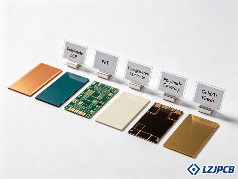
Flexible medical PCBs use seven main substrates: polyimide, liquid crystal polymer, PET polyester, PTFE-based laminates, copper foil, biocompatible coatings, and high-temperature polyamide. Polyimide leads most designs for its thermal stability, chemical resistance, and flexibility. Material choice depends on bending life, sterilization exposure, and skin or implant contact.
I have managed many projects across medical, automotive, and industrial fields. Medical flex boards carry the highest stakes. Let me walk you through the materials that keep patients safe and your devices compliant.
Why Flexible Medical PCBs Require Specialized Base Materials
A consumer flex board can fail and you lose a phone. A medical PCB flex board fails and you risk a life. That gap explains everything.
Flexible medical PCBs need specialized base materials because they must pass biocompatibility tests, survive repeated sterilization, and resist body fluids and cleaning agents. Standard flex materials crack, leach chemicals, or delaminate under these conditions. Medical-grade substrates like polyimide and LCP meet ISO 10993 and USP Class VI rules.
When I review a medical flex design, I check three things first. Will it touch the body? How will it be cleaned? Will it survive heat cycles? Each answer points to a different material path.
Biocompatibility and ISO 10993 Compliance for Implantable Devices
Biocompatibility means the material does not harm living tissue. ISO 10993 is the test standard that proves this. For implantable devices, this rule is not optional.
A material can leach ions or break down inside the body. This causes inflammation or worse. So we pick substrates that stay inert. Polyimide passes most ISO 10993 tests when paired with the right coatings.
For implants, I often add a parylene coating. Parylene gives a thin, even barrier. It blocks moisture and isolates the circuit from tissue. It also passes USP Class VI, the strictest plastic safety grade.
| ISO 10993 Test | What It Checks |
|---|---|
| Part 5 | Cytotoxicity (cell damage) |
| Part 10 | Skin irritation and sensitization |
| Part 11 | Systemic toxicity |
I always ask clients if the board sits inside the body or beside it. Implant-adjacent designs need parylene or biocompatible adhesives. Direct skin contact needs skin-safe surface materials. Getting this wrong means a failed audit.
Thermal Stability Requirements for Sterilization Cycles
Sterilization uses heat, steam, or chemicals. Autoclave cycles hit 121°C or higher. A weak material softens or warps at these temperatures.
Polyimide handles this well. It stays stable far above autoclave heat. High-temperature polyamide substrates also survive both soldering and sterilization. This is why I favor them for reusable medical tools.
PET polyester is cheaper but has a low heat limit. I only use PET for single-use, low-heat devices. If the board faces repeated autoclaving, PET is the wrong call. The glass transition temperature, or Tg, tells you the safe limit. Always match Tg to your sterilization method.
Chemical Resistance to Cleaning Agents and Bodily Fluids
Medical boards are exposed to harsh chemicals daily. Disinfectants, alcohol, and bodily fluids attack weak materials. A poor substrate swells, cracks, or loses insulation.
Polyimide resists most cleaning agents. This is one reason it dominates medical flex. For extra protection, I add epoxy encapsulation or conformal coatings. These seal the circuit from moisture and fluids.
For devices that touch skin or fluids often, I combine a polyimide base with a parylene or coverlay top layer. This layered defense keeps the copper safe. Chemical failure is slow but sure, so we plan for it from day one.
Polyimide Films vs Liquid Crystal Polymer for Medical Flex PCBs
You face a fork in the road early in design. Polyimide or LCP? Pick wrong and you overspend or you lose performance.
Polyimide suits flexible, cost-sensitive, and disposable medical devices with strong thermal and chemical resistance. Liquid crystal polymer suits implantable and high-frequency devices because it absorbs almost no moisture and holds tight dimensions. The choice depends on device lifetime, signal needs, and budget.
I get this question almost every week. Most clients start thinking LCP because it sounds advanced. But polyimide handles 80% of medical flex jobs just fine. Let me break down when each one wins.
Polyimide: Flexibility and Cost Effectiveness for Disposable Devices
Polyimide is the workhorse of medical flex PCB. It bends well, costs less than LCP, and resists heat and chemicals. For disposable devices, it is almost always my first pick.
Disposable devices need good performance at a fair price. Polyimide gives you both. A single-use sensor patch or surgical tool board does not need LCP-level moisture control. It needs reliable flex and clean signal at low cost.
Polyimide also comes in many thicknesses. This gives design freedom. I pair it with ultra-thin copper, around 9 to 18 µm, for traces that bend without fatigue. This combo handles most wearable and disposable medical needs with ease.
Liquid Crystal Polymer: Ultra Low Moisture Absorption for Implantables
LCP absorbs almost no moisture, this is its key strength. For implantable devices, this matters a lot.
Inside the body, moisture is everywhere. A material that soaks up water swells and shifts. LCP stays dry and stable. This protects long-term implants from slow failure, It also keeps signal paths exact over years.
LCP has a low dielectric constant too. This helps high-frequency signals stay clean. So for implants that also send data, LCP does double duty. It costs more, but for life-critical implants, the price is worth it.
Choosing Between Polyimide and LCP by Application Lifetime
Application lifetime is the simplest way to choose. Short life points to polyimide. Long life inside the body points to LCP.
| Factor | Polyimide | LCP |
|---|---|---|
| Cost | Lower | Higher |
| Moisture absorption | Moderate | Very low |
| Best for | Disposable, wearable | Implantable, high-frequency |
| Signal performance | Good | Excellent |
| Flexibility | Excellent | Good |
I ask clients one question. How long must this board work and where? A patch worn for a week uses polyimide. A pacemaker lead used for years uses LCP. Match the material to the mission and the rest gets easier.
High Frequency Materials for Flexible Medical PCB Antennas and Sensors
Modern medical devices talk to networks. Wireless monitors, 5G implants, MRI tools. These need materials that protect signal speed and clarity.
High-frequency flexible medical PCBs use PTFE-based laminates, controlled dielectric constant films, and LCP for low signal loss. These materials keep signal integrity in antennas and sensors. They support wearable monitors, MRI-compatible circuits, and 5G-connected devices where standard flex materials add too much loss.
When signal speed climbs, material choice gets strict. A small loss in the lab becomes a big problem in the field. I treat high-frequency medical work as its own discipline.
PTFE-Based Flex Materials for Wearable Patient Monitors
PTFE-based materials have very low signal loss. This makes them strong for wearable monitors that send data wirelessly. A heart monitor patch needs clean signals to report accurate readings.
PTFE keeps the signal sharp at high frequency. It also resists heat and chemicals. For a device worn against the skin, this matters. Sweat and cleaning still attack the board, so chemical resistance helps.
I pair PTFE with controlled impedance design. This keeps the signal path tuned. A wearable that drops or scrambles data is useless to a doctor. So we test the high-speed path early and often before mass production.
Controlled Dielectric Constant Laminates for MRI Compatible Circuits
MRI machines use strong magnetic fields. Any metal or unstable material can distort the image or react badly. So MRI-compatible circuits need careful material control.
Controlled dielectric constant laminates keep electrical behavior steady. The dielectric constant, or Dk, shapes how signals travel. If Dk drifts, the circuit behaves in ways you did not plan. For MRI tools, that risk is too high.
I use laminates with tight, known Dk values. This gives predictable signal paths. We also avoid magnetic metals near the imaging zone. Stainless steel and Invar help here, since they offer stability without strong magnetic reaction.
Signal Integrity Testing for 5G Connected Medical Devices
5G medical devices run at high data rates. Signal integrity testing proves the board can handle them. We do not guess. We measure.
At LZJPCB, we run 100% electrical testing plus AOI on flex boards. For high-speed designs, our engineers also run crosstalk and impedance checks. Our design team supports signals up to 112G. This depth matters for 5G medical work.
I tell clients that testing is not a cost, it is insurance. A 5G implant that loses packets can miss a critical alert. Flexible dielectric films with controlled impedance keep the signal honest. We verify this before the board ever ships.
Metal Foil Options for Conductive Layers in Medical Flex Circuits
The copper is the nervous system of your board. Pick the wrong foil and your traces crack after a few thousand bends. Then the device dies in the field.
Medical flex circuits use rolled annealed copper for dynamic bending, electro-deposited copper for high-density designs, and stainless steel or Invar for temperature-stable sensors. Rolled annealed copper resists fatigue best under repeated flexing. Ultra-thin copper, around 9 to 18 µm, keeps conductivity while allowing bending.
Conductor choice is where many designs quietly fail. The board works at first. Then bending fatigue sets in. I push clients to match the foil to the motion the board will face.
Rolled Annealed Copper for Dynamic Bending Applications
Rolled annealed copper, or RA copper, has a smooth grain structure. This lets it bend many times without cracking. For dynamic bending, it is the clear winner.
Dynamic bending means the board flexes again and again during use. Think of a hinge inside a device or a cable that moves with a joint. Regular copper cracks under this stress. RA copper holds up far longer.
I always specify RA copper for flex zones that move. The fatigue resistance is worth it. A monitor that bends with the patient or a tool that folds needs this foil. Skipping it leads to early failure and field returns.
Electro Deposited Copper for High Density Interconnect Designs
Electro-deposited copper, or ED copper, forms in a way that suits fine features. For high-density interconnect, or HDI, designs, ED copper works well.
HDI designs pack many traces and vias into a small area. ED copper supports the tight spacing these need. It is cheaper than RA copper too. For static designs that do not flex much, ED copper is a smart choice.
The trade-off is bending life. ED copper cracks sooner under repeated flex. So I use it for rigid-flex sections or static zones. Match it to the part of the board that stays still, not the part that moves.
Stainless Steel and Invar for Temperature Stable Medical Sensors
Some sensors must stay exact across temperature swings. Copper expands with heat. For these cases, stainless steel and Invar help.
Invar has a very low coefficient of thermal expansion. This means it barely changes size with heat. For a medical sensor that must read precisely at body temperature and room temperature, this stability matters.
Stainless steel adds strength and stability too. It resists corrosion from fluids and cleaning. I use these metals as support or sensor layers, not main conductors. They give the board a stable backbone where precision counts most.
Coverlay and Dielectric Material Selection for Patient Safety
The coverlay is the skin of your flex board. It protects the copper and keeps patients safe. A weak coverlay peels off during sterilization and exposes the circuit.
Coverlay and dielectric selection protect patient safety by sealing the circuit from moisture, fluids, and handling. Photoimageable coverlay suits fine-pitch electrodes. Adhesiveless coverlay endures sterilization better than adhesive types. Surface insulation resistance testing under humidity confirms the protection holds in real conditions.
I treat the coverlay as a safety part, not a finishing touch. It stands between the live circuit and the patient. So I choose it with the same care as the base material.
Photoimageable Coverlay for Fine Pitch Medical Electrode Arrays
Photoimageable coverlay lets us open very small, exact windows. For fine-pitch electrode arrays, this precision is key. Standard coverlay cannot match it.
Electrode arrays place many small contacts close together. Each needs a clean, exact opening. A film coverlay punched by hand cannot hold these tolerances. Photoimageable coverlay uses light to define openings, so the result is sharp.
For ECG patches or neural sensors, this matters. The contacts must align with skin or tissue points. I specify photoimageable coverlay when the pitch drops below what punched film can handle. It costs more, but it delivers the accuracy these devices need.
Adhesive vs Adheseless Coverlay for Sterilization Endurance
Adhesive coverlay uses a glue layer to bond. Adhesiveless coverlay bonds without that extra glue. For sterilization, adhesiveless usually wins.
The adhesive layer is often the weak point. Heat and steam attack it. After many autoclave cycles, the adhesive coverlay can lift or delaminate. Adhesiveless types skip this risk.
| Type | Sterilization Endurance | Cost |
|---|---|---|
| Adhesive coverlay | Lower | Lower |
| Adhesiveless coverlay | Higher | Higher |
I push clients toward adhesiveless coverlay for reusable, sterilized devices. For single-use items, adhesive coverlay can be fine. The key is matching the coverlay to how often the board faces heat. Delamination is a top cause of medical flex failure.
Surface Insulation Resistance Testing Under Humidity
Surface insulation resistance, or SIR, testing checks if the board stays insulated in damp conditions. Humidity can create leak paths between traces. SIR testing finds these before shipping.
We run SIR tests under controlled humidity and temperature. The board must hold its insulation value. If resistance drops, current can leak where it should not. In a medical device, that leak is a safety risk.
I see SIR testing as a final safety gate. A board can pass dry tests and still fail in humid use. So we test in conditions close to real life. This catches coverlay and dielectric weak spots before they reach a patient.
5 Quality Certifications to Verify for Flexible Medical PCB Substrates
A supplier can claim anything. Certifications are how you prove it. Skip the checks and you risk a failed audit or a recall.
Verify five key certifications for flexible medical PCB substrates: USP Class VI for implantable contact, REACH and RoHS for regulated market export, UL 796 for flammability, IPC 4204 for flexible dielectrics, and ISO 13485 for raw material traceability. These confirm safety, compliance, and quality control.
When I work with clients in Germany or the US, certifications come first. They protect both sides. At LZJPCB, we hold ISO 13485, ISO 9001, UL, RoHS, REACH, and more. Let me explain what each one proves.
USP Class VI Certification for Implantable Flex Circuits
USP Class VI is the top plastic safety grade. It proves a material is safe for body contact. For implantable flex circuits, this certification is a must.
The test checks for toxic reactions in living systems. A material that passes USP Class VI is cleared for the most demanding medical use. Parylene coatings and select biocompatible films carry this grade.
I never let an implant design proceed without USP Class VI on the contact materials. The risk is too high. If a supplier cannot show this certification for an implant material, walk away. There is no shortcut for body-safe parts.
REACH and RoHS Compliance for Export to Regulated Markets
REACH and RoHS control harmful substances. Europe and other regulated markets require them. Without these, you cannot legally sell there.
RoHS limits lead, mercury, and other toxic elements. REACH covers a wider list of substances of very high concern, or SVHC. We provide SVHC reports with our REACH compliance so clients can prove their supply chain is clean.
For a German buyer selling worldwide, this matters a lot. Customs and customers both check. I make sure every medical board we ship carries full REACH and RoHS documents. This keeps your export path clear and your reputation safe.
UL 796 Recognition for Flammability in Medical Enclosures
UL 796 covers printed wiring board safety, including flammability. For medical enclosures, fire safety is not optional. A board that burns puts everyone at risk.
The standard tests how the board reacts to heat and flame. A UL-recognized board resists ignition and limits flame spread. We hold UL and CUL recognition, so our boards meet this bar.
I check UL 796 for any device that holds power or sits in an enclosure. Medical equipment runs for years, sometimes nonstop. A flammability failure could cause a fire in a hospital. UL recognition gives you and your customers peace of mind.
IPC 4204 Specification for Flexible Base Dielectrics
IPC 4204 sets the rules for flexible base dielectrics, it defines how flex materials should perform. This standard helps you compare suppliers fairly.
The spec covers properties like peel strength, thermal stress, and dimensional stability. When a material meets IPC 4204, you know it hits a known quality bar. This removes guesswork from your sourcing.
I reference IPC 4204 in our flex material data sheets. It gives clients a clear way to verify what they buy. For a detail-focused buyer, this standard is a strong checkpoint. Ask your supplier which IPC 4204 type their dielectric matches.
ISO 13485 Traceability for Raw Material Batches
ISO 13485 is the quality standard for medical devices. Its traceability rules let you track every raw material batch. This is vital when problems arise.
If a defect appears, traceability lets us find the exact material lot. We can isolate the issue fast and prevent a wider recall. Our base materials from Shengyi, Isola, and others are UL and RoHS-traceable.
LZJPCB holds ISO 13485 certification. We log material batches and link them to each order. For Jerome and buyers like him, this is the proof of control they need. Traceability turns a vague promise into a documented fact.
Common Material Selection Mistakes in Flexible Medical PCB Prototyping
I have seen good designs fail at prototype because of small material errors. These mistakes cost time and money. Worse, they hide until the board is in use.
Common flexible medical PCB material mistakes include ignoring stress relief in high-flex zones, using consumer-grade adhesives that delaminate after autoclaving, and overlooking thermal expansion mismatch with components. These errors cause cracking, peeling, and joint failure. Avoid them with correct material choice and DFM review.
Our DFM process catches most of these before fabrication. I have personally fixed many designs that would have failed otherwise. Here are the three mistakes I see most often.
Ignoring Stress Relief Features in High Flexibility Zones
High flexibility zones take heavy stress. Without stress relief features, traces crack at the bend point. This is a common prototype error.
Stress relief means shaping the design to spread the bending load. Rounded corners, staggered traces, and proper bend radius all help. A sharp corner in a flex zone is a crack waiting to start.
I always review bend zones during DFM. We add stress relief where the board moves most. We also pair these zones with rolled annealed copper. This combination of smart layout and the right foil keeps the board alive through many bend cycles.
Specifying Consumer Grade Adhesives That Delaminate After Autoclaving
Consumer-grade adhesives are cheap and easy. But they fail under autoclave heat. After a few sterilization cycles, the layers peel apart.
Delamination exposes the circuit and ends the device life. I see this when clients reuse a consumer flex spec for a medical job. The adhesive that works in a phone fails in an autoclave.
For medical flex, I specify medical-grade epoxy or acrylic adhesives or adhesiveless construction. These bond layers do not give up flexibility or heat resistance. Match the adhesive to the sterilization method. Never assume a consumer adhesive will survive medical use.
Overlooking Coefficient of Thermal Expansion Mismatch With Components
Coefficient of thermal expansion, or CTE, describes how much a material grows with heat. When the board and the components have very different CTE values, stress builds at the joints. Over time, those joints crack.
This mistake hides at first. The board passes initial tests. Then heat cycles from sterilization or use slowly break the solder joints. The failure shows up months later in the field.
I check the CTE match during design. Materials like Invar help where stability is key. We also pick component packages that fit the board’s CTE. Our placement accuracy down to ±0.03mm for ICs helps, but the material match must come first. Plan for CTE early and you avoid slow joint failure later.
Conclusion
Choose flexible medical PCB materials by bending life, sterilization, signal needs, and body contact. Verify certifications. Avoid common mistakes. LZJPCB delivers compliant, durable medical flex boards.


