 Skip to content
 Your MRI image looks blurry. The signal artifacts trace back to one weak board. A poor PCB can ruin a million-dollar imaging system.
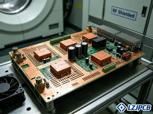
MRI machine PCBs need ultra-low EMI design, strict RF and analog isolation, high-layer multilayer stackups, and controlled impedance for the 8–128 MHz RF range. They use low-loss materials like Rogers and high-Tg FR-4, built under ISO 13485 and IPC Class 3 standards.
I have managed over 300 PCB projects in 7 years. MRI boards are some of the hardest. Let me show you what really matters, step by step.
How MRI Machine PCBs Differ from Standard Medical Device PCBs
Standard medical PCB pass basic tests. MRI boards face strong magnets and RF pulses. One wrong layout choice, and your image fills with noise.
MRI machine PCBs differ from standard medical PCBs because they need ultra-low EMI design, strict RF and analog isolation, and high-layer stackups. Strong magnetic fields and RF pulses distort signals fast when shielding, grounding, and layout are not engineered with care.
The gap between a normal medical board and an MRI board comes down to interference control, signal isolation, and long-term stability. I will break both down for you.
Medical PCB Assembly Process for MRI System Electronics
The MRI assembly process puts reliability ahead of speed. An MRI system has many subsystems. Each one needs its own board approach. The main subsystems are the RF transmit and receive chain, gradient control, main processing, power modules, and patient interface.
I run the process in clear steps:
- Start with a DFM and engineering review for each board.
- Print solder paste with automatic printers, then check with 3D SPI.
- Place parts with high-speed SMT machines at ±0.04mm accuracy.
- Run reflow with controlled 10 or 12-zone profiles.
- Add through-hole parts with selective or wave soldering.
- Inspect every board with inline AOI and X-ray for BGA joints.
- Finish with functional test and full traceability.
I keep RF circuits and sensitive receiver circuits apart during layout. This isolation protects image clarity. Every board gets a lot of records, so we can trace each part back to its source years later.
The Role of PCB Quality in MRI Image Resolution and System Stability
PCB quality drives image resolution and system stability in a direct way. A weak board adds noise. Noise lowers the signal-to-noise ratio. A low ratio gives you a blurry scan.
MRI systems work in the RF range, around 8 to 128 MHz for clinical 0.2 to 3 Tesla machines. At these frequencies, small layout errors matter. Stray capacitance, poor grounding, or weak shielding all show up as artifacts in the final image.
Here is how quality factors map to results:
| Quality Factor | Effect on MRI |
|---|---|
| Controlled impedance | Stable RF signal, sharp resolution |
| Solid ground planes | Low noise, fewer artifacts |
| Clean ionic residue | No leakage on high-impedance nets |
| RF and analog isolation | Clear receiver signal |
| Material stability | Consistent results over years |
I treat each board as part of a safety-critical system. One bad joint can stop a hospital scanner. That is why I test far beyond standard PCB QA.
MRI Machine PCB Types and Material Selection Guide
The wrong material kills your RF signal. The wrong board type cracks under thermal stress. Picking these early saves you costly redesigns later.
MRI machines use rigid, flex-rigid, and high-frequency multilayer PCBs, often 8 to 20-plus layers. Material choices include low-loss Rogers and PTFE laminates for RF boards, high-Tg and low-CTE substrates for thermal stability, and low-outgassing laminates for sealed enclosures.
Material and board type choices depend on the subsystem. RF coils need different boards from gradient control. Let me walk through each option so you can match the right one to your design.
Rigid vs Flex-Rigid PCBs for MRI Gradient and RF Coil Control
Rigid PCBs work best for control logic, power, and signal processing. Flex-rigid PCBs work best where space is tight or vibration is a risk. MRI gradient and RF coil control often need both stability and flexible routing in one assembly.
I choose based on the job:
- Use rigid boards for main control, power distribution, and gradient drivers.
- Use flex-rigid boards for RF coil interconnects and compact subassemblies.
- Use flex-rigid where the board must bend around a curved coil housing.
- Use flex-rigid where vibration during transport could crack a rigid joint.
A rigid-flex board removes connectors. Fewer connectors mean fewer failure points. For MRI coils that move or sit in tight spaces, this matters a lot. LZJPCB builds rigid-flex boards up to 14 layers, so we cover most MRI coil control needs.
Low-Outgassing Laminate Materials for Sealed MRI Enclosures
Low-outgassing laminates stop trapped gases from harming sealed MRI parts. Some MRI modules sit in sealed enclosures. Standard laminates can release gas over time. That gas can fog optics, corrode contacts, or build pressure.
I pick laminates with stable resin systems that release little gas under heat and vacuum. This keeps the sealed space clean for years. For these enclosures, I confirm the resin meets low-outgassing data before I lock the stackup.
This choice often pairs with high-Tg materials. A stable resin handles both outgassing and heat. I always check the data sheet for both numbers before quoting. Getting this wrong means a sealed module fails in the field, far from any repair shop.
High-Tg and Low-CTE Substrates for Cryogenic and Thermal Cycling Environments
High-Tg and low-CTE substrates keep the board stable under heat swings and cryogenic cooling. MRI magnets use cryogenic cooling. Other modules run hot. The board must hold its shape across this range.
A low-CTE material expands little when heated. This protects plated holes and copper from cracking. Here is how key materials compare:
| Material | Tg | CTE (Z-axis) | Best Use |
|---|---|---|---|
| Standard FR-4 | around 135°C | High | Low-stress areas |
| High-Tg FR-4 | around 175°C | Medium | Control boards |
| Rogers RO4350B | >280°C | 32 ppm/°C | RF coil boards |
I pick low-CTE, high-Tg substrates to keep signal integrity and dimensions stable under heat. This is one of the most common areas where I see design teams make costly mistakes. I will cover those errors later.
Surface Finish Options for High-Rel Medical MRI Applications
ENIG is the top surface finish for high-reliability MRI boards. It gives a flat surface, good for fine-pitch parts. It also resists corrosion and stands up to cleaning agents used in hospitals.
I match the finish to the need:
- ENIG: best for fine-pitch BGA, flat, chemical-resistant.
- Immersion silver: good RF performance, lower cost.
- Electroplated gold: hard, used for gold fingers and contacts.
- ENEPIG: best for mixed bonding and long shelf life.
I verify the finish can survive cleaning agents if the board faces them. For MRI boards exposed to hospital cleaning, ENIG is my default pick. LZJPCB supports all these finishes in-house, so I can switch based on your real use case.
How to Choose a PCB Manufacturer for MRI Machine PCBs
Pick the wrong supplier and you get inconsistent boards. You also get failed audits and missed deadlines. The right partner prevents all three from the start.
Choose an MRI PCB manufacturer that handles high-frequency design, strong thermal control, and medical-grade reliability. They must hold ISO 13485, support DFM and RF simulation, provide full traceability, and pass on-site audits. Pick vendors that explicitly mention MRI or medical imaging support, like LZJPCB.
A good supplier acts as an engineering partner, not just a fabricator. Below are the questions, the compliance checks, and the audit list I use to judge any MRI PCB partner.
7 Qualification Questions to Ask Your MRI PCB Assembly Partner
These seven questions show quickly whether a supplier can handle MRI work. I ask each one before I trust a new factory.
- Do you hold ISO 13485 for medical device manufacturing?
- Can you build controlled impedance boards within ±5 percent?
- Do you support RF-aware stackup planning and impedance simulation?
- Can you handle 8 to 20-plus-layer boards with buried vias?
- Do you offer turnkey fabrication plus assembly under one quality system?
- Can you trace every component lot from source to final board?
- Do you support rigid-flex and low-loss RF materials in-house?
If a supplier hesitates on any of these, I stop. MRI boards leave no room for guesswork. A clear yes on all seven means the supplier understands the stakes.
Evaluating Manufacturer Compliance with FDA and MDR Regulatory Frameworks
MRI boards are part of regulated medical systems. So the maker must support FDA and MDR frameworks. This means strong process control, documentation, and traceability.
I check these compliance points:
- ISO 13485 quality system, the base for medical work.
- Full lot traceability and document control.
- Long-term record retention for medical audits.
- IPC Class 3 manufacturing for safety-critical boards.
- Material certificates with UL and RoHS records.
The supplier does not certify your final device. You do that. But the supplier must give you the records and process control that your FDA or MDR file needs. I require ISO 13485-quality manufacturing because MRI boards demand this level of traceability and control. Without these records, your own audit will fail.
On-Site Audit Checklist for MRI-Compatible PCB Manufacturing Facilities
An on-site audit confirms what a supplier claims on paper. I use a fixed checklist when I visit a factory. This keeps my review fair and complete.
| Audit Area | What I Check |
|---|---|
| Quality system | ISO 13485 records, live use |
| Process control | Written work instructions |
| Traceability | Lot tracking from IQC to ship |
| Inspection | AOI, X-ray, SPI in line |
| Cleanliness | ESD control, contamination steps |
| Storage | Temp, humidity, ESD-safe |
| Test | Electrical test, functional test |
I walk the floor, not just the meeting room. I watch operators work. I ask to see real lot records. A clean audit means I can trust the supplier with safety-critical MRI boards. This is the kind of detail meticulous buyers value most.
Cost Structure for MRI Machine PCB Manufacturing and Assembly
You see a high quote and wonder why. MRI boards cost more for real reasons. Knowing the cost drivers helps you plan budgets with no surprises.
MRI PCB cost depends on material premiums, layer count, buried vias, volume, and tooling. Prototype boards run higher per unit, while volume drops the price. Low-outgassing and high-reliability materials add premiums, and complex control boards carry NRE and tooling charges.
Cost is not random. Each factor adds in a clear way. Let me break down materials, layers, volume, and tooling so you can read any MRI quote with confidence.
Material Premiums for MRI-Grade Low-Outgassing and High-Reliability PCBs
MRI-grade materials cost more than standard FR-4. Low-outgassing and low-loss laminates carry a premium. Rogers and PTFE materials cost more than FR-4 but give better RF performance.
Here is how materials compare on cost and use:
| Material | Relative Cost | Why You Pay |
|---|---|---|
| Standard FR-4 | Low | General control boards |
| High-Tg FR-4 | Medium | Heat resistance |
| Rogers RO4350B | High | Stable RF, low loss |
| PTFE | Highest | Lowest loss, hardest to process |
I choose low-loss, high-stability materials only where the design needs them. I do not put Rogers on a simple control board. Smart material mixing keeps your cost down while protecting RF performance where it counts.
Layer Count and Buried Via Impact on MRI PCB Assembly Pricing
Layer count and buried vias raise the price steeply. More layers mean more process steps. Buried and blind vias need extra lamination and drilling cycles.
MRI boards often use 8 to 20-plus layers. Each added layer adds cost. Here is the trend:
- 6 to 8 layers: moderate cost, common for control.
- 10 to 14 layers: higher cost, used for mixed signal.
- 16 to 20-plus layers: high cost, used for dense RF and data.
- Buried or blind vias: add lamination cycles and price.
I plan the stackup to hit your function with the fewest layers possible. Each extra layer and each via type adds real money. LZJPCB builds up to 32 layers in mass production, so I have room to design the right stackup, not just the cheapest.
Prototype vs Low-Volume vs High-Volume Production Cost Comparison
Per-unit cost drops as volume rises. Prototypes cost the most per board. Setup spreads over fewer units. High volume spreads tooling and setup over many boards.
Here is a rough guide based on common MRI PCB ranges:
| Stage | Per-Board Cost | Why |
|---|---|---|
| Prototype | Highest | Setup over few units |
| Low volume | Medium | Some setup spread |
| High volume | Lowest | Setup spread wide |
MRI runs are often low volume. So I plan tooling to serve both prototype and small batch well. I keep your prototype stackup the same as production. This avoids a second qualification later, which saves both time and money.
NRE and Tooling Charges Specific to Complex MRI Control Boards
NRE and tooling charges are one-time costs for setup. They cover stencils, test fixtures, programming, and DFM work. Complex MRI control boards need more of each.
These charges cover:
- Stencil and tooling for SMT setup.
- Test fixture build for functional test.
- Impedance simulation and RF stackup work.
- DFM and DFT engineering review.
- First-article inspection setup.
I spread NRE across your order where I can. For MRI control boards, the DFM and simulation work is worth it. It catches errors before production. A small upfront NRE saves a large failure cost later.
Quality Control Standards for MRI Machine PCB Assembly
A skipped test ships a weak board. That board can fail inside a scanner. Strong QC catches faults before they ever reach the hospital floor.
MRI PCB assembly needs IPC Class 3 quality, six core electrical tests, thermal shock and vibration validation, and tight ionic contamination control. Comprehensive testing goes beyond standard QA, including RF performance validation and long-duration reliability checks for hospital environments.
QC is where MRI boards earn trust. I test far past normal PCB checks. Below are the IPC classes, the electrical tests, the stress tests, and the cleanliness steps I run.
IPC Class 3 and Class 2 Requirements for MRI System Electronics
IPC Class 3 sets the bar for MRI system electronics. Class 3 covers high-reliability boards where failure is not an option. Class 2 covers general dedicated service.
Here is the split:
| Standard | Use | Acceptance |
|---|---|---|
| IPC Class 2 | General dedicated boards | Moderate, some defects allowed |
| IPC Class 3 | High-reliability, safety-critical | Tight, minimal defects |
I build MRI safety-critical boards to Class 3. The acceptance limits are tighter. Solder joints, annular rings, and plating all face stricter checks. Medical-grade work means ISO 13485 plus IPC Class 3 together. This pairing is essential because MRI equipment must stay reliable over a long service life.
6 Mandatory Electrical Tests for MRI Machine PCBs
These six electrical tests confirm a board works before it ships. I run each one on MRI boards.
- Continuity test: confirms every net connects.
- Isolation test: confirms no shorts between nets.
- Impedance test: confirms controlled impedance within ±5 percent.
- Insulation resistance test: confirms high-impedance nets hold.
- Hi-pot test: confirms the board handles voltage stress.
- Functional test: confirms the board does its real job.
I add 100 percent electrical test plus AOI as a dual check. For MRI boards in the RF front end, I also add RF performance validation. This catches signal problems that a basic test would miss. Every board leaves with a test record.
Thermal Shock and Vibration Validation for MRI Transport and Operation
Thermal shock and vibration tests prove a board survives transport and use. MRI machines ship far. They run for years. The board faces temperature swings and movement.
I run these stress tests:
- Thermal cycling: swings temperature to stress joints and vias.
- Thermal shock: fast swings to find weak points.
- Vibration test: shakes the board to mimic transport.
- Long-duration reliability test: runs the board for extended hours.
These tests find weak joints before the board reaches a hospital. A board that passes thermal cycling will hold up across cryogenic and hot zones. This is testing beyond standard PCB QA, and MRI work demands it.
Cleanliness and Ionic Contamination Control for High-Impedance MRI Circuits
Clean boards protect high-impedance MRI circuits. Ionic residue left after soldering can cause leakage. On high-impedance nets, even a small leak adds noise.
I control cleanliness with these steps:
- Wash boards to remove flux residue.
- Test ionic contamination to a set limit.
- Use ESD-safe handling at every step.
- Store boards in controlled temp and humidity.
MRI receiver circuits run at high impedance. Stray leakage there shows up as image noise. I keep ionic levels low so these sensitive nets stay clean. This step is easy to skip and costly to ignore.
MRI Machine PCB Customization and Design for Manufacturability
A great design that cannot be built wastes months. DFM bridges design and production, It turns your concept into a board that ships on time.
MRI PCB customization and DFM cover high-speed differential pair routing, smart panelization for low-volume runs, and component lifecycle management for 10-plus year systems. A strong partner adjusts design rules and plans for long-term part supply to keep MRI systems serviceable.
DFM is where my engineering team adds the most value. We tune design rules, plan panels, and manage parts. Here is how I handle each for MRI boards.
Design Rule Adjustments for High-Speed Differential Pair Routing in MRI Systems
Differential pair routing carries high-speed MRI data with low noise. The pairs must match in length and spacing. Small errors cause skew and signal loss.
I adjust design rules like this:
- Match pair lengths to cut skew.
- Hold tight spacing for stable impedance.
- Keep RF and analog circuits isolated from digital noise.
- Use solid ground planes under high-speed traces.
- Add via stitching to control return paths.
I plan RF-aware stackups and add copper shielding layers to cut EMI. Strong RF and analog isolation keep the receiver clean. For high-speed front ends, I run impedance simulations and tune material choice for RF performance. This work happens before fabrication, not after a failure.
Panelization Strategies for Medical-Grade Low-Volume MRI Production
Smart panelization saves cost on low-volume MRI runs. MRI orders are often small. A good panel layout fits more boards per panel and cuts waste.
I plan panels with these goals:
- Fit the most boards per panel without crowding.
- Add break tabs or V-cuts for clean depaneling.
- Leave room for fiducials and test points.
- Protect fine-pitch parts during routing.
For low-volume medical work, I balance panel use against handling risk. A tight panel saves material, but it must still allow safe assembly and clean separation. LZJPCB runs router and CNC depaneling, so I match the method to your board type.
Component Lifecycle Management for 10+ Year MRI System Models
Lifecycle management keeps MRI systems serviceable for over 10 years. MRI machines run for a long time, and parts can go obsolete during that life. I planned for this from the start.
I manage parts with these steps:
- Track part lifecycle status during design.
- Pick parts with long supply roadmaps.
- Plan approved alternates for risky parts.
- Stock key parts where supply is tight.
My supply chain team runs annual supplier audits and a D-grade elimination system. This keeps your part sources strong over the years. For a 10-year MRI model, I flag end-of-life risk early. This avoids a redesign when one chip disappears from the market.
MRI PCB Assembly Lead Time and Shipping for Medical Equipment
A late board delays your whole build. Long lead times hurt your market reach. Clear timing and safe shipping keep your MRI project on track.
MRI PCB prototype fabrication takes about 7 to 10 days, assembly takes 5 to 7 days, and volume production takes 3 to 6 weeks. Component sourcing drives much of the timeline. Boards ship in ESD and moisture barrier packaging with proper customs handling for regulated medical imports.
Lead time has many parts. Fabrication, sourcing, packaging, and customs all add days. Let me lay out each so you can plan your schedule with no guesswork.
Standard Lead Time Ranges for Prototype and Production Quantities
Lead time depends on stage and quantity. Prototypes move faster per board. Production needs more time for volume and testing. Here are common ranges for MRI PCB work:
| Stage | Typical Lead Time |
|---|---|
| Prototype fabrication | 7 to 10 working days |
| Prototype assembly | 5 to 7 working days |
| Volume production | 3 to 6 weeks |
LZJPCB can expedite fabrication where needed. We build 4-layer boards in 24 hours and 6-layer boards in 48 hours on rush orders. Our on-time delivery rate runs above 99 percent. For MRI work, I plan the schedule around parts, since sourcing often sets the real pace.
Component Sourcing Lead Times for MRI-Specific Active and Passive Parts
Component sourcing often drives the full MRI timeline. Some MRI-specific parts have long lead times. A board waits on its slowest part.
I manage sourcing with these steps:
- Check part lead times during the quote.
- Source from original makers and tier-1 agents.
- Confirm parts are genuine and traceable.
- Plan alternates for long-lead parts.
- Stock key parts to cut wait time.
My team kits samples in as fast as 3 days when stock allows. For MRI boards, I flag long-lead parts early. This lets us order ahead and keep the build moving. Genuine parts matter here, since a fake part in an MRI system is a safety risk.
ESD and Moisture Barrier Packaging for MRI PCB Shipment
ESD and moisture barrier packaging protect MRI boards in transit. Static can damage sensitive parts. Moisture can harm boards and parts during long shipping.
I pack MRI boards like this:
- Seal boards in moisture barrier bags.
- Add desiccant to control humidity.
- Use ESD-safe trays and bags.
- Add humidity indicator cards.
- Cushion boards against shock and vibration.
This packaging keeps boards safe from the factory to your dock in Germany. For sensitive MRI receiver boards, this care matters. A board damaged by static or moisture in transit is a hidden cost you want to avoid.
Logistics and Customs Clearance for Regulated Medical PCB Imports
Good logistics planning speeds customs for regulated medical PCBs. Medical imports face extra checks. Clear paperwork keeps your shipment moving.
I prepare these for smooth clearance:
- Accurate commercial invoice and packing list.
- Correct HS codes for PCB and PCBA.
- Material and compliance certificates.
- RoHS and REACH records were needed.
I ship to the USA, Europe, Brazil, and Russia, so I know the paperwork each region wants.
LZJPCB Capabilities for MRI Machine PCBs
You need a partner who has done this before. Not every factory can build MRI boards. LZJPCB brings the experience and certs your project demands.
LZJPCB provides turnkey PCB manufacturing and assembly for MRI and medical imaging systems. We support multilayer RF-grade boards, precision SMT, strict traceability, and scalable production from prototype to mass volume. We hold ISO 13485, ISO 9001, IATF 16949, UL, RoHS, and REACH certifications.
We work as your engineering partner, not just a fabricator. We offer DFM, RF simulation support, and long-term lifecycle help. Here is what we bring to your MRI project.
MRI PCB Manufacturing and Assembly Expertise
LZJPCB builds the full range of MRI boards under one roof. We have made medical MRI control boards and medical device ceramic boards. Our team carries real medical imaging experience.
Our capabilities cover:
- Multilayer boards up to 32 layers in mass production.
- Controlled impedance within ±5 percent.
- Low-loss RF materials like Rogers and PTFE.
- Rigid-flex boards up to 14 layers.
- SMT at 8 million placements per day with ±0.04mm accuracy.
- AOI, X-ray, SPI, and functional test in line.
We offer turnkey fabrication plus assembly. This keeps stackup, fabrication, and test under one quality system. For MRI work, that single-system control lowers your risk. We also give you a dedicated engineer for custom development, which most website-based competitors do not.
Compliance and Quality Certifications
LZJPCB holds the certifications for MRI work demands. Our ISO 13485 certification covers medical device quality. This is the base standard for MRI boards.
Our certifications include:
| Certification | What It Covers |
|---|---|
| ISO 13485 | Medical device quality |
| ISO 9001 | General quality system |
| IATF 16949 | Automotive-grade process control |
| ISO 14001 | Environmental management |
| UL and CUL | Safety standards |
| RoHS and REACH | Material compliance with SVHC reports |
We also hold over 20 patents and rank as a China National High-Tech Enterprise. Our client list includes Mindray and Foxconn. For your MRI project, these certs give you the traceability and process control your own audit needs.
MRI Machine PCB Assembly: Common Mistakes and FAQ
Small mistakes cause big MRI failures. A wrong CTE spec or stray capacitance can ruin an image. Knowing these traps saves you costly rework.
The most common MRI PCB mistakes are wrong CTE specification, ignored stray capacitance, and unclear design files. Stray capacitance is a leading cause of signal artifacts. LZJPCB supports prototypes with no MOQ and reviews standard design files through a full DFM process.
I have seen these mistakes hurt real projects. Let me share the worst ones and answer the questions buyers ask most.
4 Costly Errors in Specifying Material CTE for MRI PCBs
Wrong CTE specs cause cracks and failures under heat. CTE is how much a material expands when heated. A mismatch stresses joints and vias. Here are four errors I see often:
- Picking a high-CTE material for a board that faces thermal cycling.
- Mixing materials with very different CTE in one stackup.
- Ignoring Z-axis CTE, which cracks plated holes.
- Skipping CTE checks for cryogenic MRI zones.
I choose low-CTE, high-Tg substrates to keep dimensions stable under heat. For MRI boards near cryogenic cooling or hot power modules, this choice protects the board for years. A CTE mistake shows up late, often after the system ships. That makes it one of the most expensive errors to fix.
Why Stray Capacitance Is a Leading Cause of MRI Signal Artifacts
Stray capacitance adds unwanted signal paths that create artifacts. It forms between traces, planes, and parts. On sensitive MRI receiver circuits, this stray path adds noise.
I cut stray capacitance with these steps:
- Keep RF and analog circuits well isolated.
- Use solid ground planes for clean return paths.
- Space sensitive traces away from noisy nets.
- Add shielding layers where needed.
MRI receiver circuits run at high impedance. Stray capacitance there shows up as artifacts in the image. Strict RF and analog isolation is the main defense. I plan this isolation in the layout stage, since fixing it later means a full redesign.
FAQ: MOQ Policy and Prototype Setup Fees for MRI PCBs
LZJPCB supports prototypes with no minimum order quantity. You can order a single prototype to test your design. We do not force a large first run.
Here is how our policy works:
- No MOQ, so you can start with one board.
- Samples kitted in as fast as 3 days when stock allows.
- Setup fees cover stencils, fixtures, and DFM work.
- We spread NRE across your order where we can.
For MRI development, this flexibility helps. You validate the board first, then scale up. We keep your prototype stackup the same as production. This avoids a second qualification and saves you time and cost later.
FAQ: Design File Format Requirements and DFM Review Process
We accept standard design files and run a full DFM review. Send us Gerber files, drill files, a BOM, and a stackup target. We check each for manufacturability before we build.
Send us these for a fast quote:
- Gerber and drill files.
- Bill of materials with part numbers.
- Stackup targets and impedance needs.
- Current load and signal frequency range.
- Mechanical constraints and compliance needs.
Our 50-plus engineers run DFM on every project. We flag issues early and suggest fixes. When you send full details up front, we confirm feasibility fast. For MRI boards, this early review catches RF and material issues before they cost you a redesign.
Conclusion
MRI machine PCBs demand ultra-low EMI design, RF isolation, controlled impedance, and ISO 13485 quality. LZJPCB delivers turnkey MRI boards from prototype to mass production.


