 Skip to content
 You design a hematology analyzer. The board fails a count. The patient gets the wrong result. One weak PCB can break your whole reputation.
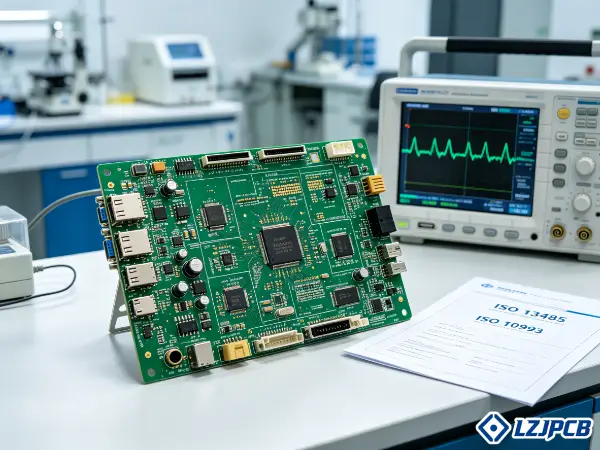
Choose a medical-grade PCB for a hematology analyzer by putting signal integrity, reliability, and regulatory readiness first. Pick boards built and assembled under ISO 13485 quality controls, with IPC Class 3 processes, full traceability, and medical-device testing before acceptance.
I have managed over 300 PCB projects across 20 countries. Many were medical PCB boards. Below I show you what really matters, step by step, so you do not learn it the hard way.
What Defines a Medical Grade PCB for Hematology Analyzers
A normal board may pass a basic test, a medical board cannot afford a single bad joint. In diagnostics, one defect means a wrong blood result.
A medical-grade PCB for a hematology analyzer is a board built to IPC Class 3 and ISO 13485 controls, with high signal integrity, strong material stability, full traceability, and testing that proves it works in a sensitive diagnostic instrument.
The core idea is simple. These boards process tiny measurement signals. A small noise spike can change a cell count. So the bar for quality sits much higher than consumer electronics.
Critical Performance Parameters for Diagnostic Equipment
A hematology analyzer reads very small electrical signals from blood cells. The board must keep these signals clean. I always check a few key numbers first.
- Signal-to-noise ratio: the board must keep noise low so weak cell signals stay readable.
- Impedance tolerance: ±5% or tighter holds the signal stable across the board.
- Insulation resistance: it must stay in the megohm range to stop leakage current.
- Plating thickness: 25µm inside through-holes protects the path under thermal stress.
- Operating life: the board should run for years without failure.
These numbers are not just nice to have. A weak plating can crack after many heat cycles. A loose impedance value can shift a reading. I treat each one as a pass or fail line, not a soft target. When I review a hematology board, I match every spec to a real test. If a supplier cannot show data, I do not trust the claim. This is how I protect both the test result and the patient who waits for it.
Regulatory Standards for In Vitro Diagnostic PCB Components
A hematology analyzer is an in vitro diagnostic device. So the board must follow medical rules, not just electrical ones. This is the part many buyers miss.
| Standard | What It Covers | Why It Matters |
|---|---|---|
| ISO 13485 | Medical device quality system | Proves the factory controls every step |
| IPC Class 3 | Highest fabrication and assembly grade | Zero cosmetic defect tolerance |
| IEC 60601-1 | Medical electrical safety | Protects users and patients |
| FDA 21 CFR Part 820 | US quality requirements | Built on ISO 13485 |
| RoHS / REACH | Hazardous substance control | Limits unsafe materials |
I tell every client to confirm ISO 13485 first. The FDA uses it as the base for its own rules. Then I check IPC Class 3, since medical diagnostic gear needs the strictest workmanship. IEC 60601-1 adds electrical safety on top. You should make your supplier prove each one with a current certificate. Ask for the scope too. A certificate that does not cover PCB fabrication or PCBA assembly means little. I have seen buyers trust a logo and regret it later.
Why Hematology Analyzers Demand Higher Signal Integrity
A hematology analyzer counts and sizes blood cells. It does this by detecting tiny changes in voltage or impedance. Even a small electrical noise can ruin the count.
This is why I push signal integrity so hard. The board processes sensitive measurement data that interference can corrupt. To protect it, I use a clear set of rules:
- Use controlled impedance routing to keep signal paths stable.
- Add dedicated ground planes to give clean return paths.
- Keep return paths short so noise does not build up.
- Use solid power planes to hold voltage steady.
- Build low-noise layouts that keep weak signals safe.
The biggest gain comes from one move. I make the analog and digital sections physically and electrically separate. The measurement front-end stays away from the data-processing logic. This cuts crosstalk and stops digital noise from leaking into the sensitive analog path. The result is a cleaner reading and better diagnostic precision. I have seen a board fail random counts only because analog and digital shared one messy ground. After we split the domains, the noise vanished. Signal integrity is not a luxury here. It is the difference between a correct result and a wrong one.
6 Essential Specifications to Evaluate in a Hematology Analyzer PCB
You can lose weeks chasing the wrong specs. Material, finish, impedance, and stackup all matter. Miss one and the board fails in the lab.
The six key specifications are material grade, surface finish, controlled impedance, layer stackup, EMI/EMC control, and thermal management. Each one protects signal integrity and long-term reliability inside a sensitive hematology analyzer.
I review these six in every medical project. Let me break down the most important ones, so you know what to ask for and why each choice changes the outcome.
Material Selection: High-TG FR4 vs. Polyimide for Medical Devices
The base material sets the limit for the whole board. Pick a weak laminate and nothing else can save it. I always start material talks early.
| Material | Best Use | Key Strength | Watch Out |
|---|---|---|---|
| High-Tg FR4 | Most analyzer boards | Good thermal and cost balance | Limited at extreme heat |
| Polyimide | High-heat or flex zones | Strong heat resistance | Higher cost, moisture care |
| Rogers / PTFE | High-frequency sections | Low signal loss | Needs special handling |
For most hematology analyzers, I choose High-Tg FR4. It gives long-term stability, good thermal resistance, and reliable work in a lab. It also keeps costs sane. I move to polyimide only when a section runs hot or needs to flex. Polyimide handles repeated heat well, but it absorbs moisture, so the factory must control drying before soldering. For any high-frequency front-end, a low-loss laminate helps protect weak signals. My rule is simple. Match the material to the real stress on each zone, not to a default choice. A good supplier will give you batch traceability on the laminate too. That paper trail matters during a medical audit.
Surface Finish Choices for Long-Term Reliability in Wet Chemistry Environments
A hematology analyzer lives near reagents and moisture. The surface finish must resist corrosion for years. The wrong finish ages fast and fails.
I prefer ENIG surface finish whenever I can. Here is why it wins:
- ENIG gives a flat surface for fine-pitch parts.
- It offers strong solderability for reliable joints.
- It resists oxidation and corrosion in wet areas.
- It holds up well over a long service life.
ENIG (electroless nickel immersion gold) beats standard finishes like HASL in medical work. HASL leaves an uneven surface and can carry lead worries. In a hematology analyzer, parts sit close together and signals run weak, so flatness and clean joints really matter. For some boards I also look at ENEPIG or immersion silver, but ENIG remains my default for high-reliability medical assemblies. I once saw a board with a cheap finish corrode near a reagent line within months. The fix cost far more than the finish upgrade would have. So I treat the finish as a long-term reliability choice, not a small line item.
Controlled Impedance and Its Role in Accurate Cell Counting
A hematology analyzer counts cells by reading tiny signal changes. If impedance drifts, the signal shifts, and the count goes wrong. So impedance control is not optional.
I require controlled impedance routing on every measurement path. The goal is a stable, repeatable signal. I aim for tight tolerance, often ±5% or better. To hold that, the factory must control trace width, dielectric thickness, and layer spacing with care. A loose process gives a board that reads fine in one spot and drifts in another.
I also pair impedance control with short return paths and solid ground and power planes. This keeps the signal clean from source to sensor. For high-speed digital links, I add differential pair matching, often 100 ohms across the pair. I ask suppliers for test coupons with measured impedance data. That proof shows the board met the target, not just the design intent. In cell counting, a stable signal means a stable count. I never let this spec slide.
Layer Stackup Design for Noise Reduction in Analog Front-End Circuits
The analog front-end reads the weakest signals on the board. A bad stackup lets noise flood in. A smart stackup keeps that signal safe.
I choose multilayer PCB designs with optimized stackups. Hematology analyzers often need 7 to 14 layers to support signal integrity, EMI control, and dense parts. I use the stackup to separate analog, digital, power, and ground domains. Each domain gets its own space.
- Place a solid ground plane next to each signal layer.
- Keep analog signal layers away from noisy digital layers.
- Give the power plane a tight pair with the ground.
- Route the analog front-end over a clean, quiet ground.
- Use the stackup to control impedance at the same time.
This layout cuts noise coupling between the measurement circuits and the data-processing logic. The front-end stays quiet, so weak cell signals stay readable. I also add EMI controls here, like a good grounding strategy, shielding, ferrite beads, and common-mode chokes where needed. The stackup and the EMI plan work together. When I design a medical board, I lock the stackup early, since changing it late breaks impedance and timing. A clean stackup is the backbone of a precise analyzer.
How to Compare Medical PCB Manufacturers for Hematology Projects
Many factories say they do medical work. Few can prove it. Pick the wrong one and you face rework, delays, and failed audits.
Compare medical PCB manufacturers by checking ISO 13485 certification, IPC Class 3 capability, cleanroom standards, HDI and blind via skills, and full component traceability. Demand proof and documents, not just marketing claims.
I have audited many factories. The good ones answer fast and show data. The weak ones go vague. Here is how I run a fair comparison so you avoid a costly mistake.
Audit Checklist: Cleanroom Standards and Quality Management Systems
A medical board needs a clean, controlled process. Dust and poor control cause hidden defects. So I audit the system, not just the price.
Use this checklist when you compare suppliers:
- Confirm a current ISO 13485 certificate and check its scope.
- Confirm IPC Class 3 fabrication and assembly capability.
- Ask about cleanroom class for assembly, such as ISO Class 7.
- Check ISO 9001 and ISO 14001 for base quality and environment.
- Ask how they handle non-conforming boards and corrective action.
- Review process validation records like IQ, OQ, and PQ.
I choose a manufacturer that follows ISO 13485 and medical-grade quality systems. A hematology analyzer is a diagnostic device, so PCB reliability ties straight to test accuracy and patient outcomes. At LZJPCB we hold ISO 9001, ISO 14001, IATF16949, and ISO 13485, plus UL and CUL marks. That mix shows a real quality culture across industries. When I audit, I ask to see records, not just the wall plaque. A factory that retrieves a production record fast has true control. One that fumbles for files does not. The system tells the truth.
Evaluating Technical Capabilities for Complex HDI and Blind Via Designs
Hematology analyzers pack many parts into small spaces. That needs HDI skill, fine lines, and tight vias. Not every factory can hold these specs.
| Capability | What to Ask | LZJPCB Capability |
|---|---|---|
| Layer count | Max layers in mass production | Up to 32L mass, 40L proto |
| Min trace/space | Fine line ability | 3/3 mil |
| HDI types | Stacked or staggered vias | 1+N+1, 2+N+2, 3+N+3 |
| Blind/buried vias | Process maturity | Supported with back drill |
| Impedance control | Tolerance held | ±5% |
| Laser via | Microvia size | Down to small laser holes |
If your board must fit a dense instrument design, ask about HDI capability, fine line and space, blind and buried vias, and high-Tg or specialty laminates. I push suppliers to show real process data, not theory. I ask how they prevent drill breakout and lifted rings. At LZJPCB, we build high-layer-count, high-frequency, HDI, and rigid-flex boards, with a design team of 50+ engineers. We support up to 28 layers in design and very fine features. This depth lets us shrink an analyzer board without losing reliability. When a supplier can match your hardest spec on paper and in samples, you have found a real partner.
Questions to Ask About Component Sourcing and Traceability
A great board with fake parts is still a failed board. Counterfeit or untracked parts ruin medical trust. So I dig hard into sourcing.
Ask these questions before you commit:
- Where do you buy parts, from original makers or tier-1 agents?
- Can you prove every part is genuine and traceable?
- How do you handle BOM and offer alternative parts?
- Do you run incoming quality control on every lot?
- How do you store parts for ESD and moisture safety?
- Can you trace a part lot to a single board serial number?
I select a supplier with full traceability and regulatory documentation support. This means material tracking, production records, inspection reports, and quality documents for audits. At LZJPCB, we run a 20+ person supply chain team. We buy from original makers and tier-1 agents, so parts stay 100% genuine and traceable. We add IQC inspection, FIFO storage, and ESD-safe, climate-controlled warehousing. We also support turnkey BOM procurement and smart alternative selection. For a hematology analyzer, this control protects both the result and the audit trail. I never let an unknown part enter a medical build.
How Much Does a Medical Grade PCB Cost for Hematology Analyzer Production?
Price looks simple until you see the hidden costs. A cheap board can trigger rework, recalls, and lost trust. The real cost hides below the quote.
A medical-grade PCB for a hematology analyzer costs more than a standard board, often 15–40% above Class 2, driven by material grade, layer count, volume, and Class 3 testing. Non-compliance costs far more through rework and liability.
I help clients see total cost, not just unit price. Below I break the cost into clear parts so you can plan a budget that protects quality and still makes sense.
Cost Breakdown: Material Grades vs. Production Volume
Two big levers drive PCB cost: material grade and order volume. Push quality up and unit cost rises. Push volume up and unit cost falls.
| Cost Driver | Low Cost | Higher Cost |
|---|---|---|
| Material | Standard FR4 | High-Tg, polyimide, Rogers |
| Layer count | 4–6 layers | 10–14+ layers |
| Surface finish | HASL | ENIG, ENEPIG |
| Volume | Mass production | Prototype runs |
| Class | IPC Class 2 | IPC Class 3 |
| Testing | Basic ET | Full medical test suite |
IPC Class 3 adds real cost over Class 2, often 15–40%. That money buys cross-section checks, tighter tolerance, and more testing. For a hematology analyzer, I treat this as money well spent, not waste. High-Tg material and more layers also raise cost, but they protect signal integrity. Volume works the other way. A prototype run carries high setup cost per board, while a mass run spreads it thin. My advice is to lock the design early, then scale volume to drop unit cost. At LZJPCB, we move from prototype to mass production under one roof, so the cost curve stays smooth as you grow.
The Real Cost of Non-Compliance: Rework and Liability Risks
A cheap board can cost the most in the end. A wrong blood result is a patient safety event. The fallout dwarfs any savings on the board.
Think about what a failed medical board can trigger:
- Rework the cost to fix or rebuild bad boards.
- Scrap cost when boards cannot be saved.
- Delay cost when shipments stop and lines wait.
- Recall cost if defective units reach the field.
- Liability cost if a wrong result harms a patient.
- Brand cost when buyers lose trust in your device.
I have seen a buyer chase the lowest quote and lose far more on rework. A supplier whose price sits 30% below qualified peers likely cuts corners on testing or traceability. In medical work, that gap is a warning, not a deal. The boards either meet Class 3 or they do not. So I choose a partner who builds it right the first time. The real cost of non-compliance lands long after the cheap quote feels good. I always price in this risk.
MOQ Considerations for Prototype vs. Mass Production Runs
Medical projects move from prototype to volume in stages. A high minimum order can block early testing. So MOQ flexibility matters a lot.
In the prototype stage, you need small runs to test the design and pass first-article checks. A factory that forces a large minimum order hurts you here. At LZJPCB we support prototyping with no minimum order quantity. We can kit samples in as fast as 3 days and build single or double-sided prototypes in 24 hours. This lets you iterate fast and fix issues early, when fixes are cheap.
For mass production, you want stable cost and steady supply. Here a higher volume drops the unit price and smooths the schedule. The key is one partner who handles both stages with the same quality system. That way, your prototype and your volume boards share the same process and traceability. I tell clients to plan the volume ramp early. Confirm that the supplier can scale without changing the validated process. A smooth jump from prototype to mass production keeps both cost and quality under control.
5 Critical Quality Tests for Hematology Analyzer PCBs
A board can look perfect and still hide a fault. Hidden defects show up in the field, where they hurt most. Testing finds them first.
The five critical tests are electrical testing, AOI, X-ray inspection, environmental stress screening, and cleanliness testing. Together they catch open circuits, hidden solder voids, thermal weakness, and contamination before the board ships.
I require a full test plan on every medical build. Below I explain the tests that catch the faults a buyer fears most, and how to make sure your supplier runs them right.
Electrical Testing: Flying Probe vs. Fixture Methods
Electrical testing finds opens and shorts. Both methods work, but each fits a different stage. I pick based on volume and timing.
| Method | Best For | Speed | Setup Cost |
|---|---|---|---|
| Flying probe | Prototype, low volume | Slower per board | Low, no fixture |
| Fixture (bed-of-nails) | Mass production | Very fast per board | High upfront |
| ICT | Functional checks on PCBA | Fast | High program cost |
For a hematology analyzer, I run 100% electrical testing, never a sample only. Flying probe suits early runs because it needs no custom fixture, so it starts fast and costs less upfront. As volume grows, a fixture test runs faster per board and lowers cost at scale. On the assembled board, I add ICT to check parts in circuit. I require AOI, X-ray inspection, ICT, functional test, and environmental stress screening before acceptance. At LZJPCB, we run 100% electrical test plus AOI as a dual inspection. This layered approach catches the opens and shorts that a single test might miss. I treat full electrical coverage as a hard rule for medical boards.
Environmental Stress Screening for Temperature and Humidity Fluctuations
A lab is not a calm place. Temperature swings and humidity stress the board over years. Environmental tests show how it ages before it ships.
I push boards through stress that mimics real life:
- Thermal cycling, often 100 cycles, to expose weak joints.
- Continuity checks before and after to catch any breaks.
- Humidity aging, like 85°C and 85% RH, for damp climates.
- Insulation resistance checks to confirm no leakage.
- Data logging on temperature for the full record.
A hematology analyzer may run for years without rest. So I ask for thermal management features too, like thermal vias and copper pours, when the unit runs continuously. Stress screening finds early failures that normal testing misses. A joint that passes at room temperature can crack after many heat cycles. By forcing that aging in a chamber, we find the weak board in the factory, not in the customer’s lab. At LZJPCB, we keep records and data logs from environmental testing, which become part of your medical file. I never skip this step on a diagnostic board.
Cleanliness Testing: Ionic Contamination and Its Impact on Leakage Current
A clean board looks the same as a dirty one to the eye. Hidden flux residue can cause leakage current. That leakage can shift a sensitive reading.
This matters a lot in a hematology analyzer. Leakage current can corrupt the weak signals the board must read. So I require ionic contamination testing after assembly. The common ROSE test checks for ionic residue left from soldering. Class 3 work limits ionic contamination to a tight number, below 1.56 µg/cm². Residue above that can cause corrosion and leakage over time.
The fix is a clean process. I ask suppliers to use aqueous cleaning followed by a DI water rinse. This removes flux residue without harsh chemicals. After cleaning, the board is ready for conformal coating where reagents may reach it. I treat cleanliness as a measured spec, not a guess. A board can pass every electrical test and still fail in the field from contamination. So I make my supplier prove the board is clean with real data. In diagnostics, a clean board protects a clean result.
How to Verify Supplier Compliance with FDA and ISO 13485 Standards
A certificate on a wall means little alone. You must verify the system behind it. Trust without proof leads to failed audits and bad boards.
Verify supplier compliance by reviewing the ISO 13485 certificate and scope, checking the Design History File and Device Master Record support, conducting a quality audit, and confirming a strict change control process. Demand documents you can show your own auditors.
I treat verification as real work, not a checkbox. Below I show the documents and steps that prove a supplier can truly support a medical device program like yours.
Documenting the Design History File and Device Master Record
Your PCB supplier’s records become part of your regulatory file. The FDA and EU auditors will ask for proof. So the supplier’s documents must be ready and clean.
I confirm the supplier can support these records:
- Material batch numbers for laminate, finish, and solder.
- Process parameters like plating thickness and reflow profiles.
- Test data for continuity, insulation, and function.
- Equipment and operator IDs on critical steps.
- Inspection reports and cross-section images.
- Deviation records with cause and disposition.
These records feed your Design History File and your Device Master Record. When a regulator asks how you ensure the electronics are reliable, this paperwork is your answer. At LZJPCB we provide material tracking, production records, inspection reports, and the quality documentation needed for medical compliance and audits. We can retrieve a production record fast, which shows real control. I tell clients to test this early. Ask for a sample document package before you place a big order. A supplier who delivers clean records now will deliver them during your audit too. This support saves you weeks when you file with the FDA or CE.
Conducting a Supplier Quality Audit for Medical Device Components
A paper review is not enough. You must see the system in action. A real audit shows whether the quality is true or just claimed.
When I audit a supplier, I look for clear signs:
- Test equipment on site, like AOI, flying probe, and X-ray.
- Environmental chambers for thermal and humidity tests.
- Trained staff who speak clearly about IPC and process control.
- A document system that retrieves records in minutes.
- DFM review offered as part of the quote.
- Fast, clear communication with English-speaking engineers.
I verify the supplier can support ISO 13485, IEC 60601-1, and FDA quality expectations for medical equipment. I also watch for red flags. A supplier with no ISO 13485 and a vague quality story is a risk. A quote far below qualified peers usually means cut corners. At LZJPCB, our engineers join the project early and give DFM feedback, unlike platforms that only take web orders. This 1-on-1 support is our edge. During an audit, I want to talk to engineers, not just sales. The depth of their answers reveals the depth of their quality. A strong audit gives you confidence that holds up under pressure.
Understanding the Importance of Change Control Notifications
A small change can break a validated board. A new material or process can add a hidden defect. So change control protects you after the first good run.
This is a quiet but vital part of ISO 13485. Any real change, like a new material supplier, an equipment upgrade, or a process tweak, must follow a formal procedure. The supplier must assess the impact, define test work, make the change, and confirm quality stays the same. Without this, a casual change can slip a latent fault into your boards.
I always confirm the supplier will notify me before any change that affects the board. For a hematology analyzer, a silent material swap could shift impedance or aging behavior. That could change a reading months later. So I write change control into the supply agreement. The supplier must send a change notification and wait for my approval on key items. This keeps the validated process locked. A good partner sees this as normal medical practice, not a burden. When a supplier respects change control, your boards stay consistent across every batch and every year.
Customization and Lead Time Management for Medical PCB Orders
A custom medical board needs care, not speed alone. Rush it and you skip key checks. Plan it well and you hit both quality and schedule.
Manage customization and lead time by starting with an engineering DFM consultation, setting realistic first-article inspection timelines, and using strict ESD-safe packaging. Early design support prevents respins that blow up your schedule.
I guide clients through this with a clear plan. Below I show how the right process protects your timeline while keeping the medical quality bar high.
The Engineering Consultation Process for Design for Manufacturability
The best time to fix a board is before it is built. A DFM review catches problems early, when fixes are cheap. Skip it and you pay later in respins.
I run DFM as a real conversation, not a form. Here is the flow:
- Share your design files and target specs with the engineers.
- The team reviews trace width, spacing, vias, and stackup.
- They flag any feature that risks low yield or failure.
- They suggest material, finish, and via options for your needs.
- They confirm impedance and thermal plans match the build.
- You approve the changes before production starts.
This early work prevents costly delays and early defects. A DFM review once caught a via placement flaw on a heart monitor board and saved weeks of testing. At LZJPCB, our DFM process and 50+ engineer team make this our core strength. Competitors often rely on web-based ordering with no real consultation. We give you a dedicated engineer who makes sure the board delivers the exact function you need. For a hematology analyzer, this support matters most, since the design carries real medical risk. I treat DFM as the cheapest insurance you can buy.
Setting Realistic Lead Times for First-Article Inspection
A first article proves the design before volume. Rushing it hides risk. A realistic timeline protects the whole program.
The first-article inspection (FAI) checks the first built board against every spec. It confirms the process makes a good board before you scale. I tell clients to plan time for this step, not squeeze it. A proper FAI includes electrical test, AOI, X-ray, and a full document review. If something fails, you fix it now, not after a thousand boards ship.
At LZJPCB we move fast where we can. We build single or double-sided prototypes in 24 hours, four-layer boards in 24 hours expedited, and six-layer in 48 hours. We hold a 99%+ on-time delivery rate. But for a medical first article, I still set a realistic window that includes full inspection and report generation. Speed and quality must balance. I plan the schedule backward from your launch date, with FAI as a fixed checkpoint. A clear FAI plan means no surprises when you move to volume. This is how I keep both the timeline and the quality intact.
Packaging and Shipping Protocols to Prevent ESD Damage
A perfect board can die in transit. Static and moisture can ruin sensitive parts. So packaging is part of quality, not an afterthought.
Medical boards carry fine, sensitive components. A single ESD hit can damage a part without any visible sign. I require strict protective handling:
- Use ESD-safe bags and trays for every board.
- Add moisture-barrier packaging with desiccant where needed.
- Mark packages with handling and ESD warnings.
- Use anti-static, climate-controlled storage before shipping.
- Apply QR-based traceability so each unit tracks back to its lot.
I request traceability, documentation, and medical-grade QC protocols, including ESD-controlled handling and QR-based traceability. At LZJPCB we store parts and boards in ESD-safe, temperature and humidity-controlled space with FIFO flow. This care protects the board from the factory floor to your city dock. For a global B2B flow, this matters even more, since the board may travel far. I have seen boards arrive dead only from poor packaging. So I treat shipping as the last quality gate. Good packaging keeps the value you paid for all the way to your hands.
Common Mistakes to Avoid When Sourcing PCBs for Hematology Analyzers
Smart buyers still make costly errors. Small oversights in heat, coating, or parts planning cause big field failures. I have seen each one hurt a project.
The most common mistakes are ignoring thermal management for high-speed parts, skipping conformal coating in reagent areas, and failing to plan for component obsolescence. Each one can cause field failures and supply shocks later.
I want you to skip the pain I have watched others feel. Below I cover the three mistakes that hurt most, and how to avoid each one with a simple plan.
Overlooking the Thermal Management Requirements of High-Speed Components
High-speed parts run hot. A hematology analyzer may run all day. Without a heat plan, the board ages fast and signals drift.
Heat is a silent killer on a busy analyzer. Hot parts shorten life and shift readings. So I build a thermal plan from the start:
- Add thermal vias under hot parts to move heat to inner layers.
- Use copper pours and planes to spread heat wide.
- Pick High-Tg material to handle steady heat better.
- Place hot parts away from the sensitive analog front-end.
- Confirm via size and spacing balance heat and signal needs.
I ask for thermal management features when the analyzer runs continuously. A board that overheats can give a wrong count, since heat changes signal behavior. At LZJPCB we use copper coin methods, via-in-pad designs, and copper pours to spread heat while keeping electrical separation. We can also use metal core boards when a section runs very hot. The key is to plan heat early, in the stackup and layout, not patch it later. A cool board is a stable board. I never let thermal planning slip to the end of a project, because by then it is too late to fix cleanly.
Ignoring the Need for Conformal Coating in Reagent Exposure Areas
A hematology analyzer works with liquids and reagents. Moisture and chemicals attack bare boards. Without coating, corrosion and leakage follow.
Conformal coating is a thin protective layer over the board. It blocks moisture, dust, and chemical splash. In a hematology analyzer, some board areas sit near reagent lines. Those zones face real exposure risk. A bare board there can corrode, and corrosion leads to leakage current that ruins a reading.
I plan coating into the design, not as an afterthought. I mark which zones need coating and which parts must stay clear, like connectors. The factory must clean the board first, since coating over flux residue traps contamination. A clean board, then a proper coat, gives lasting protection. The coating must also survive the lab environment over years. At LZJPCB we offer conformal coating, underfill, and potting for moisture and contamination protection. I treat coating as a core spec for any analyzer board near reagents. It is a small step that prevents a slow, hidden failure. Skipping it to save a little is a mistake I see too often.
Failing to Plan for End-of-Life Component Obsolescence
A medical device sells for many years. Parts, though, can vanish from the market. If a key part goes obsolete, your line can stop.
This is a long-term trap many buyers ignore at the start. A hematology analyzer may ship for a decade. But chip makers retire parts on their own schedule. If you have no plan, a single obsolete part can halt production. I help clients build a defense:
- Track lifecycle status of every critical part in the BOM.
- Identify single-source parts that carry the most risk.
- Choose alternative parts and validate them early.
- Hold safety stock of high-risk, long-lead components.
- Watch for end-of-life notices from makers.
- Keep a strong supply partner who can find replacements.
At LZJPCB, our 20+ person supply chain team supports turnkey BOM procurement and smart alternative selection, with tens of thousands of stock items. We can flag risky parts during the BOM review and suggest validated alternatives. This early work keeps your line running for years. I tell clients to treat obsolescence as a design input, not a future surprise. A part chosen well at the start saves a crisis later. Planning for end-of-life is how you protect a long product life and steady supply.
Conclusion
Choose a hematology analyzer PCB by putting signal integrity, ISO 13485 quality, IPC Class 3, full testing, and traceability first. LZJPCB delivers all of this, from prototype to volume.


