Skip to content
Your LED headlights dim too soon. Heat kills brightness and shifts color, the PCB inside is often the real reason.
Automotive LED headlight PCB assembly is the process of mounting LEDs and driver parts onto a heat-managing board, usually an aluminum metal core PCB, then soldering, testing, and building it into a lighting module that survives heat, vibration, and a -40°C to 125°C life.
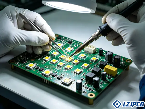
I have managed over 300 PCB projects in seven years. Many of them were lighting boards. Let me show you what really matters when you source them.
What Is Automotive LED Headlight PCB Assembly?
Headlights run hot. A weak board traps that heat. Your LEDs fade, shift color, and fail early. The board choice decides the outcome.
Automotive LED headlight PCB assembly mounts LEDs, drivers, and protection parts onto a thermally optimized board, then solders and tests them into a module. It uses metal core boards because high-power LEDs need strong heat removal to stay bright and live long.
Let me break the parts, the steps, and the differences down so you can talk to any supplier with confidence.
Key Components of an Automotive LED Headlight PCB
A headlight board is more than LEDs. Each part has a job. Together they keep the light stable and safe.
- High-power LEDs: The light source. They produce strong heat at the junction that the board must carry away.
- LED driver IC: Controls current to the LEDs. It keeps brightness steady when voltage moves.
- Thermal pads and copper fill: Spread heat from the LED into the metal base.
- Protection parts: Diodes and filters guard against load-dump and switching noise.
- Connectors: Link the board to the harness and dimming control.
The board structure has three main layers. A copper circuit layer carries current. A dielectric layer insulates but still passes heat. An aluminum base spreads heat to the housing or heatsink. This stack is why metal core boards beat standard FR4 for lighting. The copper is often 2oz or thicker. Thick copper carries high LED current and helps spread heat sideways before it reaches the base. I always check that the thermal pad under each LED matches or beats the LED package pad. A bigger pad means lower thermal resistance and a cooler junction.
The Assembly Process: From SMT to Reflow Soldering
Assembly is a chain. One weak link causes hot spots or dead boards. A good line controls every step.
Here is the typical flow I run for headlight boards:
- Solder paste printing: A stencil lays paste on pads. We use 80-90% coverage on big thermal pads to avoid voids.
- SMT placement: Machines place LEDs and small parts with high accuracy.
- Reflow soldering: The board passes through an oven. Metal core boards need a longer preheat because the metal holds heat.
- AOI inspection: Cameras check placement and solder joints.
- X-ray inspection: This finds hidden voids under thermal pads and BGAs.
- Functional and electrical test: We power the module and check light output and current.
Quality-focused assembly adds full traceability so each board links back to its batch. I avoid wave soldering on metal core boards. The long heat exposure can weaken the dielectric bond. Reflow with a tuned profile is the safe choice. Our SMT lines run YAMAHA machines, 3D SPI, inline AOI, and X-ray. This setup lets us catch defects before they ship, which matters most in safety parts like headlights.
Why Automotive PCBs Differ From Consumer PCBs
Consumer boards live in calm rooms. Car boards live in heat, salt, and shaking. The rules are not the same.
Automotive headlight PCBs must survive far harsher stress than consumer boards. They face vibration, moisture, road salt, and temperature cycling from about -40°C to 125°C for the whole life of the car. A phone board never sees this.
| Factor | Consumer PCB | Automotive Headlight PCB |
|---|---|---|
| Temp range | 0°C to 70°C | -40°C to 125°C |
| Vibration | Low | High, up to 20G |
| Quality system | ISO 9001 | IATF 16949 |
| Reliability proof | Basic | AEC-Q102, thermal cycling |
| Traceability | Optional | Full batch tracking |
The quality system is the big split. Consumer work often runs on ISO 9001 alone. Automotive PCB work needs IATF 16949. That standard focuses on defect prevention and tight supplier control. Headlight boards also need EMI and EMC control. The car’s electrical system is noisy, and the board must not interfere with other electronics. I treat every headlight board as a safety part. A failed headlight at night is a real danger. So the testing and material rules stay strict from the first prototype.
Automotive LED Headlight PCB Material Selection
The wrong materials absorb heat, which reduces brightness and lifespan. Your material choice sets the limit before you even place an LED.
For automotive LED headlights, choose aluminum-core or copper-core PCBs over FR4 because metal cores move heat far better. Aluminum is the common pick. Copper goes into ultra-high-power designs where space is tight and heat is extreme.
Let me compare the main options so you can match the board to your power and shape needs.
Aluminum-Based vs FR4 PCBs for Thermal Management
FR4 is cheap and common, but it holds heat like a blanket. For high-power LEDs, that is a problem you cannot ignore.
Standard FR4 has a thermal conductivity of only 0.3-0.4 W/mK, this creates a heat bottleneck between the LED and the heatsink. Metal core boards solve this. An aluminum or copper base carries heat at 120-400 W/mK and sends it straight to the chassis or housing.
| Property | FR4 | Aluminum Core | Copper Core |
|---|---|---|---|
| Base conductivity (W/mK) | 0.3-0.4 | 138-167 | ~391 |
| Cost | Lowest | Low | 4-5x aluminum |
| Weight | Light | Light | Heavy |
| Best use | Low-power signals | Most headlights | Ultra-high power |
I prefer aluminum-core or copper-core boards for high-power headlight designs because they give better thermal conductivity. Excessive junction temperature is the enemy. It reduces brightness, shifts color, and shortens LED life. The dielectric layer matters too. A standard epoxy gives 1.0-1.5 W/mK. A ceramic-filled type reaches 2.0-4.0 W/mK but costs more. For under-hood or engine-bay heat, I also push for materials with high thermal stability and corrosion resistance. The aluminum base must be treated to stop oxidation, which would block heat transfer.
Single-Layer vs Double-Layer vs Multilayer Headlight PCBs
More layers mean more control. They also add cost and thermal resistance. The right count depends on how smart your lighting must be.
- Single-layer aluminum: The simplest and best for pure thermal jobs. One copper layer sits on the dielectric and base. It gives the shortest heat path.
- Double-layer: Adds a second copper layer with a prepreg. It allows more routing but adds a little thermal resistance.
- Multilayer: Needed for smart lighting. Adaptive Driving Beam (ADB) and matrix LED systems need high-density boards to support control logic and driver electronics.
Modern headlights are getting smarter. ADB and matrix systems are pushing demand for high-density designs that can run intelligent lighting. These often mix a thermal section for the LEDs with a denser section for the controller. I match the layer count to the function. A basic high-beam module may need only one layer. A matrix headlight with per-pixel control needs many. We build 1 to 40 layers, so I can scale the design to fit either a simple lamp or a complex matrix system without forcing a costly stack the project does not need.
Flexible and Rigid-Flex PCBs for Complex Headlight Designs
Some housing curves and twist. A flat rigid board will not fit. Flex and rigid-flex solve tight mechanical problems.
Flexible LED PCBs bend to follow curved trim and bodywork. Rigid-flex boards combine a rigid board and its interconnect cable into one part. This cuts connectors, which are common failure points under vibration.
- Flexible PCB: Best for curved DRL strips and ambient trim that must follow the body shape.
- Rigid-flex PCB: Best when a module needs both a stiff LED section and a flexible link to the connector.
- Rigid aluminum: Best for the main high-power headlamp where heat is the top concern.
I verify the supplier can produce rigid, flex, or rigid-flex options when the module has tight mechanical limits. Not all factories can do all three well. Our Shenzhen base runs a dedicated FPC factory with a Class 100K cleanroom. We build flex from 1 to 8 layers and rigid-flex from 0.25 to 6.0mm thick. This lets me design a single module that mixes a thermal LED zone, a flexible bridge, and a connector area. One part replaces three, which raises reliability in a shaking headlight housing.
How to Choose the Right Automotive LED Headlight PCB for Your Vehicle
A board that fits one car may fail in another. Wattage, housing, and control all change the spec. Pick wrong and you waste a full production run.
Choose your automotive LED headlight PCB by matching its thermal capacity to the LED wattage, its electrical specs to the system voltage, and its driver interface to your dimming control. Send your housing geometry and thermal limits so the supplier can match the board to the optic and heatsink.
Let me walk through the three checks I run before I approve any headlight board for production.
Matching PCB Specifications to Headlight Housing and Wattage
The board must fit the box and carry the heat. A mismatch creates hot spots or a part that will not mount. Both kill the project.
I start with the LED power and the housing shape. The thermal pad size and copper weight follow the wattage:
| LED Power | Thermal Pad Size | Copper Weight |
|---|---|---|
| 0.5-1.5W | 3×3 to 4×4 mm | 1 oz |
| 3-5W | 5×5 to 7×7 mm | 2 oz |
| Over 5W | 8×8 mm or larger | 3 oz |
The metal base thickness matters too. For boards up to 100x100mm, 1.5-2.0mm aluminum balances heat spreading with rigidity against vibration. I space LEDs at least 10-15mm apart to stop thermal crosstalk between them. The board must also fit the housing and contact the heatsink cleanly. I require thermal design support for the PCB-to-heatsink interface, since headlight performance depends on heat removal. This is why I ask clients to send the stackup, BOM, LED current targets, thermal limits, and housing geometry up front. With that data, my engineers match the board to the optic and heatsink instead of guessing.
Key Electrical Parameters: Current and Dielectric Strength
Current sets the trace size. Dielectric strength sets the safety margin. Get these wrong and you risk a short or a breakdown.
The dielectric layer must block voltage while still passing heat. For automotive use, the breakdown voltage should exceed 2500 VAC. A high-performance board targets over 4.0 kV.
- Current capacity: Trace width follows IPC-2152 with a 20°C rise limit. Wide, thick traces cut resistive heating.
- Dielectric strength: Standard dielectric gives over 3 kV/mm. This stops breakdown under high voltage.
- Isolation clearance: A 12V system needs 0.5mm trace clearance. A 48V system needs 1.0mm. Over 60V needs 1.5mm.
I ask for automotive-grade reliability evidence, including temperature-range validation and long-life testing. These electrical specs are not just numbers. They decide if the board survives a load-dump spike or a long, hot drive. The glass transition temperature, or Tg, also matters. A standard board sits at 130°C. A high-performance one runs over 170°C. For under-hood heat, I push for the higher Tg. It keeps the board stable when the ambient heat climbs.
Compatibility with LED Drivers and Dimming Control Systems
The board and driver must speak the same language. A mismatch causes flicker or dead channels. Smart headlights make this harder.
The driver controls the current to keep the brightness steady when the car’s voltage moves. The board layout must support the driver’s needs and protect against noise. Surge protection and EMC filtering keep the module stable in real vehicle conditions.
- Confirm driver topology: Linear or switching drivers need different layouts and thermal plans.
- Plan for dimming: PWM dimming needs clean signal routing to avoid flicker.
- Add EMC filtering: Filtering reduces interference with other car electronics.
- Support smart control: ADB and matrix systems need dense routing for per-pixel control.
I run a DFM review, thermal simulation, and functional testing before production to avoid hot spots and early failure. This step catches driver and layout conflicts early. For matrix headlights, the board must carry control signals to many LED groups at once. I design the routing so each channel stays clean and the heat stays even. A 1-on-1 review with my engineers is where I catch most driver mismatches before they reach the factory floor.
Total Cost of Automotive LED Headlight PCBs
Price shock is common. A cheap quote often hides poor thermal design. The real cost shows up later as field failures and recalls.
The total cost of an automotive LED headlight PCB depends on base material, layer count, copper weight, dielectric grade, and surface finish. Aluminum costs more than FR4, copper costs 4-5x aluminum, and ceramic dielectric adds a 2-3x premium.
Let me show you where the money goes so you can balance price against reliability.
Base Material Cost: Aluminum Substrate vs Standard FR4
FR4 wins on raw price, but it loses heat. The cheaper board often costs more over the product’s life.
Aluminum substrate costs more than FR4 up front. But for high-power LEDs, FR4 cannot dissipate the heat, so it is not a real option. The cost split sits in the base metal and the dielectric.
| Material | Relative Cost | Notes |
|---|---|---|
| FR4 | Lowest | Poor heat removal |
| Aluminum 5052 | 1.0x | Standard headlight base |
| Aluminum 6061 | 1.2x | Better machining and heat |
| Copper C11000 | 4.5x | Ultra-high power only |
The dielectric layer adds its own cost. Standard epoxy is the baseline. Ceramic-filled epoxy costs about 1.5x, high thermal ceramic costs about 2.5x. I only specify the ceramic dielectric when the standard material cannot hit the junction temperature target, usually in compact arrays above 20W total power. A low-bid supplier may use recycled or off-spec substrate to cut costs. That choice creates inconsistent heat removal and field failures. The Total Cost of Ownership matters more than the unit price. I always weigh the quote against the risk of a recall, which can dwarf the part savings.
How Layer Count and Surface Finish Affect Unit Pricing
Each layer adds process steps. Each finish has a different price and life. These choices move the unit price up or down.
Layer count drives cost. A single-layer aluminum board is the cheapest to build. A multilayer board for matrix lighting needs more lamination, drilling, and inspection, so it costs more.
- Single-layer: Lowest cost, best for pure thermal headlamps.
- Double-layer: Moderate cost, allows more routing.
- Multilayer: Highest cost, needed for ADB and matrix control.
Surface finish also shifts the price:
- ENIG: The automotive standard. Great solderability and long shelf life.
- OSP: Cheaper but short shelf life and needs careful handling.
- HASL: Avoid on metal core boards. The thermal shock can stress the dielectric bond.
I pick ENIG for most headlight boards because it survives automotive testing and stores well. The copper weight matters too. Heavier copper carries more current but is harder to etch, which raises cost. My job is to find the lowest cost that still meets the thermal and reliability targets. I do not cut the dielectric grade or the finish just to win a quote. That trade always costs the client more in the field.
6 Quality Certifications and Tests for Automotive LED Headlight PCBs
A pretty board can still fail in a car. Only testing proves it will last. Certifications show the factory can repeat that quality every time.
Automotive LED headlight PCBs need IATF 16949 and ISO 9001 quality systems, plus thermal cycling, humidity, Hi-Pot, insulation resistance, and optical alignment tests. These prove the board survives heat, moisture, and vibration over the vehicle’s life.
Let me explain the key certifications and tests, and why each one protects your project.
IATF 16949 and ISO 9001: Mandatory Quality Management Standards
ISO 9001 is a start. It is not enough for cars. IATF 16949 is the standard that automotive buyers demand.
IATF 16949 is the global quality standard built for the automotive industry. It focuses on defect prevention, less variation, and strict supplier control. ISO 9001 is more general and aims at customer satisfaction.
| Feature | ISO 9001 | IATF 16949 |
|---|---|---|
| Scope | General | Automotive |
| Focus | Satisfaction | Defect prevention |
| Supplier control | General | Strict |
| Audit intensity | Standard | High, with core tools |
An ISO 9001-only supplier lacks the automotive rigor of APQP, FMEA, and PPAP. For a safety part like a headlight, that gap is too big. I ask whether the line supports automotive quality systems such as IATF 16949 and automotive validation practices. The audit checks if a factory can hold quality from the first prototype to the millionth unit. LZJPCB earned IATF 16949 in 2023, along with ISO 9001 and ISO 14001. Automotive-grade LED PCB makers increasingly chase IATF 16949 and IPC-A-600 Class 3 to meet OEM and Tier-1 demands. I treat these as the entry ticket, not a bonus.
Thermal Cycling and Humidity Tests for Headlight Durability
Cars heat up and cool down all day. Moisture creeps in too. These tests prove the board survives that endless cycle.
Thermal cycling per AEC-Q102 runs 1000 cycles from -40°C to +125°C with 30-minute dwells. This stresses the bond between the aluminum base, the dielectric, and the copper because each layer expands at a different rate.
- Thermal shock cycling: Rapid swings from -40°C to +125°C test the layer bonds.
- Humidity test: 85°C and 85% RH for 1000 hours stresses the dielectric and LED seal.
- HTOL: A long bias test predicts the dielectric’s life and the MTBF.
I ask for failure analysis reports with cross-section images that show the aluminum-to-dielectric bond after cycling. A weak bond delaminates and creates hot spots. Conformal coating adds moisture protection, but it must handle over 100°C and not block heat. Parylene or silicone coatings are common for these boards. I push for this evidence because a board that passes a quick test but fails after 500 cycles is worse than useless. It fails in the field, where a recall is expensive and a dark headlight is a real hazard.
Hi-Pot and Insulation Resistance Testing
Voltage finds weak spots. A pinhole in the dielectric becomes a short. Hi-Pot testing finds that flaw before the car does.
Hi-Pot testing applies a high voltage across the dielectric to confirm it holds. For automotive boards, the dielectric should block over 2500 VAC. This test proves the insulation will not break down under a voltage spike like a load-dump event.
- Hi-Pot test: Applies high voltage to find dielectric weak points.
- Insulation resistance test: Measures how well the dielectric blocks prevent leakage current.
- Pass target: Breakdown voltage over 2500 VAC, often over 4.0 kV for high-performance boards.
The dielectric layer is the most critical material in the board. It must insulate and still pass heat, which is a hard balance. A thin dielectric moves heat better but risks breakdown. A thick one is safer but holds more heat. I check that the supplier runs Hi-Pot on production lots, not just samples. A single void in the dielectric, often from trapped air during lamination, can fail this test. We use vacuum lamination and strict surface prep to keep the dielectric clean and void-free. That process control is what makes the Hi-Pot pass rate stable across a full production run.
Optical Alignment and Light Output Consistency Checks
The light must point the right way. Each LED must match its neighbor. A small placement error ruins the beam pattern.
Optical alignment checks confirm the LEDs sit in the exact spots the optic needs. A shifted LED throws the beam off and can blind oncoming drivers or leave dark gaps. Light output consistency checks confirm each LED gives the same brightness and color.
- Optical alignment check: Confirms LED placement matches the optic design.
- Light output test: Powers the module and measures brightness across all LEDs.
- Color consistency check: Confirms color temperature stays in spec across the array.
I add optical alignment marks to the board so the assembly machine and the optic both register to the same points. These checks matter most in matrix headlights. There, many small LEDs must each hit a target zone on the road. One misplaced LED breaks the pattern. Our line uses inline AOI and 3D SPI to catch placement errors before reflow. After assembly, we power the module and check the light. I treat the beam pattern as a pass-fail gate. A board that lights up but aims wrong is a failed board, no matter how clean the solder looks.
How to Verify an Automotive PCB Manufacturer: 5 Supplier Audit Questions
A slick website hides a lot. The real test is the factory floor. Five sharp questions separate a true partner from a risky bet.
Verify an automotive PCB manufacturer by asking for material test reports and RoHS proof, checking their production capacity, auditing the SMT line, and reviewing their sample approval process. Confirm IATF 16949 and request failure analysis evidence.
Let me give you the four audit areas I check before I trust any factory with a headlight order.
Material Test Reports and RoHS Compliance
Marketing claims are cheap, material reports are proof. Without traceable data, you cannot trust the board’s heat or safety performance.
A reputable maker provides a Certificate of Conformance for every material lot. It lists chemical makeup, thickness tolerance, and thermal conductivity. This proves the aluminum and dielectric match the spec, not a cheaper substitute.
- Certificate of Conformance: Confirms each material lot meets the spec.
- RoHS and REACH proof: Confirms the board is free of banned substances.
- Conflict mineral compliance: Covers tin, tantalum, tungsten, and gold.
- Lot-level traceability: Links each board back to its raw material batch.
I require material test reports and RoHS compliance for every headlight order. Inconsistent copper purity hurts adhesion and resistance, which causes intermittent LED failures under thermal cycling. We use base materials from Shengyi, Nan Ya, KB, and other A-grade suppliers, all UL and RoHS traceable. We also hold REACH compliance with SVHC reports. This paper trail is not bureaucracy. When a board fails in the field, traceability lets us isolate one batch instead of recalling everything. That surgical recall ability is a real cost saver for a buyer like you.
Evaluating Production Capacity for Large-Scale Headlight Orders
A great prototype means little if the factory cannot scale. Headlight orders run into the millions. The line must hold quality at volume.
I check the monthly capacity against my forecast. A factory that struggles at volume will cut corners or miss dates. IATF 16949 exists to prove a maker can hold quality from the first prototype to the millionth unit.
- Monthly board output: Confirms the factory can meet your volume.
- SMT placement rate: Shows how fast the line builds modules.
- Dedicated NPI line: Lets prototypes run without stopping mass production.
- Multiple sites: Spreads risk and adds surge capacity.
Our PCB base in Ji’an covers 15,000 square meters and runs over 2,500 models and 50,000 square meters per month. Our SMT lines place 8 million parts per day. We run three PCBA factories plus an overseas base in Indonesia. This scale lets me promise a buyer that a pilot run and a full production run get the same quality. I confirm the supplier can handle SMT assembly plus post-soldering, testing, and final module build in one workflow. A one-stop flow removes the gaps where quality slips between vendors.
On-Site Factory Audit: What to Check on the SMT Production Line
You learn the most by walking the floor. Photos hide dust and chaos. An on-site audit shows the truth a remote review cannot.
An on-site audit gives unfiltered views of the floor culture, cleanliness, and maintenance. For headlight boards, the most critical thing to check is thermal interface handling and dielectric bonding pressure. Bad handling here causes catastrophic thermal failure.
Here is my SMT line audit checklist:
- Equipment calibration: Confirm presses and etching lines were calibrated in the last 6 months.
- Contamination control: Check dust filtration in the lamination cleanroom.
- AOI and X-ray: Confirm the line runs automated inspection on every board.
- Solder paste control: Check paste storage and stencil cleaning.
- Traceability: Confirm they can track a board back to the copper foil batch.
I treat the audit as non-negotiable for a new headlight supplier. A remote audit is fine for checking paperwork, but it cannot catch operator discipline or contamination on the floor. When clients visit our Bao’an base, I walk them through the SMT line and show the SPI, AOI, and X-ray stations live. Seeing the inspection run on a real board builds more trust than any brochure. I want the buyer to see the process, not just the result.
Sample Approval Process: Prototype Run and First Article Inspection
Mass production starts with one approved sample. Skip this step and you risk a full bad batch. The sample is your safety gate.
A solid sample process runs a prototype, then a First Article Inspection before mass production starts. This confirms the design works and the line can build it right. PPAP documentation backs this up in automotive work.
- Prototype run: Builds a small batch to prove the design.
- First Article Inspection: Checks the first units against every spec point.
- Thermal verification: Some makers run thermal imaging on the sample to confirm heat transfer.
- Sign-off: The buyer approves before volume starts.
I run a DFM review, thermal simulation, and functional testing before production to avoid hot spots and early failures. The sample stage is where I catch most problems. A thermal image of the sample shows hot spots that a spec sheet hides. I also ask for thermal impedance testing on production lots so quality stays stable, not just on the sample. Our samples can be kitted in as fast as 3 days, with no minimum order. This lets a buyer like you test a real board before committing to a large run. I never push a client to skip the First Article step to save time. That shortcut always backfires.
Customization Options for Automotive LED Headlight PCB Orders
A stock board rarely fits a custom housing. Your headlight is unique. The board must bend to your design, not the other way around.
Automotive LED headlight PCB orders support custom shapes, custom hole drilling, white silk screen with optical alignment marks, and anti-static packaging. These options let the board fit a specific housing and ship safely without damage.
Let me cover the main customization choices I offer so your board matches your exact module.
Custom Shape and Hole Drilling for Specific Headlight Enclosures
Headlight housings are odd shapes, a rectangular board will not fit a curved lamp. Custom routing and drilling solve the fit problem.
I cut the board to match the enclosure exactly. The mounting holes must align with the housing and the heatsink. Hole placement also affects vibration resistance. I put mounting holes 20-30mm from the LED positions to cut board flex under vibration.
- Custom outline: CNC routing cuts the board to fit the housing shape.
- Mounting holes: Drilled to match the heatsink and housing points.
- Edge finish: Aluminum edges need clean routing to avoid burrs that cause shorts.
- Heat sink contact: Some designs expose metal edges for chassis grounding.
Aluminum is rigid, so bad CNC routing causes burrs or delamination at the dielectric edge. That flaw leads to shorts when the board mounts in the housing. We run high-RPM spindle control to prevent thermal micro-cracking in the aluminum. Our CNC precision holds a ±0.05mm tolerance, which ensures a tight fit and vibration resistance. I always ask the client for the housing geometry early. With the 3D shape in hand, my team cuts a board that drops into the lamp with no rework. A good fit also improves the heatsink contact, which keeps the LEDs cool.
White Silk Screen and Optical Alignment Marks
Marks guide the machines, they also guide the assembly and the optics. Clear marks cut errors and speed up the line.
A white silk screen makes part labels and marks easy to read against the board. Optical alignment marks, called fiducials, give the SMT machine and the optic a shared reference point. This keeps LED placement accurate.
- White silk screen: High-contrast labels for parts and polarity.
- Optical alignment marks: Fiducials guide precise LED placement.
- Polarity marks: Prevent reversed LED or part placement.
- Optic registration marks: Help align the lens to the LED array.
These marks matter most in matrix and ADB headlights, where many LEDs must each hit a target zone. A shared reference point keeps the whole array aligned to the optic. I add the marks during the DFM review so the assembly machine and the optic register to the same spots. This is a small detail with a big payoff. It cuts placement errors, which protects the beam pattern. A clean silk screen also helps during repair and inspection, since techs can read every label. I treat these marks as part of the quality plan, not just cosmetics.
Packaging and Anti-Static Shipping for Delicate PCB Assemblies
The board can survive the road but die in the box. Static and shock kill assembled boards. Good packaging protects your work in transit.
Assembled headlight boards carry sensitive driver ICs and LEDs. Static discharge can damage them in shipping. So I pack them in anti-static, ESD-safe materials. The packaging also guards against shock and moisture during the long trip to Germany or the US.
- ESD-safe bags: Protect the board from static damage.
- Moisture barrier: Guards humidity-sensitive parts in transit.
- Shock protection: Foam or trays stop impact damage.
- Clear labeling: Lot codes support traceability on arrival.
Our warehouse runs FIFO with temperature, humidity, and ESD control. This care extends from storage to the shipping box. I match the packaging to the order. A small prototype run ships in simple ESD trays. A large production run uses custom trays that protect each board and speed up the client’s incoming inspection. I have seen boards arrive damaged from poor packing, and the rework cost more than the packaging would have. So I treat packaging as the last quality step, not an afterthought. The board you approved must reach you in the same condition.
Common Mistakes to Avoid When Sourcing Automotive LED Headlight PCBs
Smart buyers still make costly errors. The mistakes hide in the details. Knowing them early saves you money and reputation.
The most common sourcing mistakes are overlooking thermal path design, ignoring CTE mismatch with the housing, and confusing IPC Class 2 and Class 3 acceptance criteria. Each one leads to early LED failure or a rejected batch.
Let me explain each mistake and how I help clients avoid it before it costs them a run.
Overlooking Thermal Path Design Leading to LED Lumen Degradation
Heat is the silent killer. A bad thermal path traps it. Your LEDs slowly fade and shift color long before they should fail.
LEDs conduct heat straight through the PCB, not by radiation like old bulbs. If the board cannot move that heat, the junction temperature climbs. This causes phosphor degradation, color shift, and permanent lumen loss. Reducing thermal resistance by even 2-3°C/W can extend LED life by 30-50%.
- Maximize pad size: A bigger thermal pad lowers thermal resistance.
- Use thick copper: It spreads heat sideways before the dielectric.
- Pick the right dielectric: Higher conductivity moves more heat.
- Control the TIM: The heatsink interface needs proper bond line thickness.
I see this mistake most when a buyer picks a board on price alone. A low-bid supplier may use a thin or cheap dielectric that traps heat. The board looks fine at first, then dims in the field. I require thermal design support for the PCB-to-heatsink interface because performance depends on heat removal. My team runs a thermal simulation before production to find hot spots. This catches the problem on screen, not in a customer’s car. The visible sign of bad thermal design is yellowing of the lens or fast dimming after power-up.
Ignoring Coefficient of Thermal Expansion Mismatch with Housing
Different materials grow at different rates with heat. That mismatch creates stress. Over thousands of cycles, the stress cracks solder joints and delaminates layers.
The aluminum base, copper layer, and ceramic LED package all have different CTE values. Aluminum sits near 23.8 ppm/°C, copper near 17, and the ceramic LED package near 6-8. As the board heats and cools, these layers expand by different amounts. This creates mechanical stress that cracks solder joints.
| Material | CTE (ppm/°C) |
|---|---|
| Aluminum base | 23.8 |
| Copper layer | 17.0 |
| Ceramic LED package | 6-8 |
The CTE of the dielectric must match the aluminum base closely to prevent delamination. A thicker dielectric layer adds mechanical compliance to absorb the stress, but it trades off thermal performance. I balance these in the design. The mismatch with the housing matters too. The board must mount in a way that allows for expansion without building stress at the mount points. I see buyers ignore this and then face solder joint fatigue that shows up only after months in the field. The thermal cycling test catches this risk before production. I always confirm the supplier runs the full -40°C to +125°C cycle and shows cross-section proof of bond integrity.
Miscommunication on IPC Class 2 vs Class 3 Acceptance Criteria
Class 2 and Class 3 are not the same. The gap is wide. A mix-up means you pay for one grade and accept another, or you reject a good batch.
IPC Class 2 covers general reliable products. IPC Class 3 covers high-reliability products where failure is not acceptable, like safety parts. Headlights are safety parts, so I often spec Class 3. The criteria differ in solder joint, annular ring, and defect tolerance.
- State the class up front: Write Class 2 or Class 3 in the order.
- Match the inspection: Class 3 demands tighter AOI and X-ray limits.
- Confirm both sides agree: A mismatch causes rejected batches or disputes.
- Document the criteria: Put the acceptance rules in writing.
Automotive makers increasingly chase IPC-A-600 Class 3 to meet OEM and Tier-1 demands. The mistake happens when a buyer assumes Class 3, but the order says Class 2. The factory builds to the lower grade, and the boards fail incoming inspection. I prevent this by confirming the class in writing before the quote. I also confirm the inspection method matches the class. A 1-on-1 review with my engineers settles this early. We agree on the exact acceptance criteria, so there is no surprise when the boards arrive. Clear communication here saves a full batch from rejection.
Common Mistakes When Sourcing Automotive LED Headlight PCBs
The same traps catch buyers again and again. Heat, expansion, and class confusion lead the list. Let me restate the core risks so they stick.
The core sourcing risks are thermal path design flaws, CTE mismatch between the PCB and housing, and IPC Class 2 versus Class 3 confusion. All three cause field failures or rejected batches if you miss them.
Let me reinforce these three risks with the practical checks I use on every headlight order.
Thermal Path Design Flaws Leading to LED Degradation
A flawed thermal path is the top cause of early LED failure. The heat has nowhere to go. The LED cooks itself slowly.
The heat path runs from the LED junction, through the solder, through the dielectric, into the aluminum base, and out to the heatsink. Every interface adds resistance. A flaw at any point traps heat and degrades the LED.
- Check the solder joint: It needs full wetting under the thermal pad.
- Avoid dielectric voids: Trapped air during lamination kills heat transfer.
- Size the pad right: Match or beat the LED package pad.
- Verify the TIM: The heatsink interface needs proper torque and bond line.
Dielectric voids are a critical defect that cuts thermal performance. They come from trapped air or contamination during lamination. We use vacuum lamination to prevent them. I require thermal impedance testing on production lots to confirm the dielectric bonds well every time. The thermal flaw is dangerous because it hides at first. The board passes a quick test, then fails after months. So I run thermal simulation in design and thermal imaging on samples. This catches the flaw before it ships. A cool junction is the single best predictor of long LED life.
CTE Mismatch Between PCB and Housing
The board and housing expand at different rates. They fight each other with every heat cycle. That fight cracks joints and loosens mounts.
When the board mounts into the housing, the two materials expand by different amounts as they heat. If the mount design does not allow for this, stress builds at the mount points and the solder joints. Over thousands of cycles, this stress causes fatigue cracks.
- Allow for expansion: Design mounts that flex with thermal growth.
- Match dielectric to base: Keep the CTE close to prevent delamination.
- Use compliant dielectric: A thicker layer absorbs stress.
- Test the full cycle: Run -40°C to +125°C and check the bonds.
The CTE mismatch is worse with copper-core boards because copper differs more from the ceramic LED package. So I weigh the higher heat removal of copper against the higher stress risk. For most headlights, aluminum gives a better balance. I confirm the supplier runs the AEC-Q102 thermal cycle and shows cross-section micrographs of the aluminum-to-dielectric interface after cycling. This proof tells me the bond survives the mismatch. I also review the housing mount design with the client. A small change to the mount points can release a lot of stress and add years of life to the module.
IPC Class 2 vs Class 3: Miscommunication Risks
A simple class mix-up wrecks a batch. Both sides assume different rules. The boards arrive and the inspection fails.
The risk is pure miscommunication. The buyer assumes Class 3, the order says Class 2, and the factory builds the lower grade. The boards then fail the buyer’s incoming inspection. Or the reverse happens, and good Class 2 boards get rejected against Class 3 rules.
- Write the class clearly: Put IPC Class 2 or Class 3 in the purchase order.
- Agree on acceptance limits: Document the exact defect criteria.
- Match inspection to class: Class 3 needs tighter AOI and X-ray limits.
- Confirm before quoting: Settle the class before the price is set.
Class 3 is the high-reliability grade for products where failure is not acceptable. Headlights are safety parts, so I usually recommend Class 3. But I never assume. I confirm the class in writing during the first review. This single step prevents a costly batch rejection. A 1-on-1 talk with my engineers locks down the criteria so both sides build to the same standard. Competitors who rely on web order forms often skip this step. That gap is where the mix-up happens. My direct review closes that gap before it costs the client a run.
Conclusion
Pick aluminum core boards, demand IATF 16949, prove the thermal path, and confirm the IPC class. Strong heat removal keeps your headlights bright and safe for life.